App-27
IM 760201-01E
Appendix
3
2
1
4
5
6
7
8
9
10
11
12
13
14
App
Index
Setting the Synchronization Period When Measuring the Efficiency of a
Power Conversion Device
• Power Transformer with Single-Phase Input and Single-Phase Output
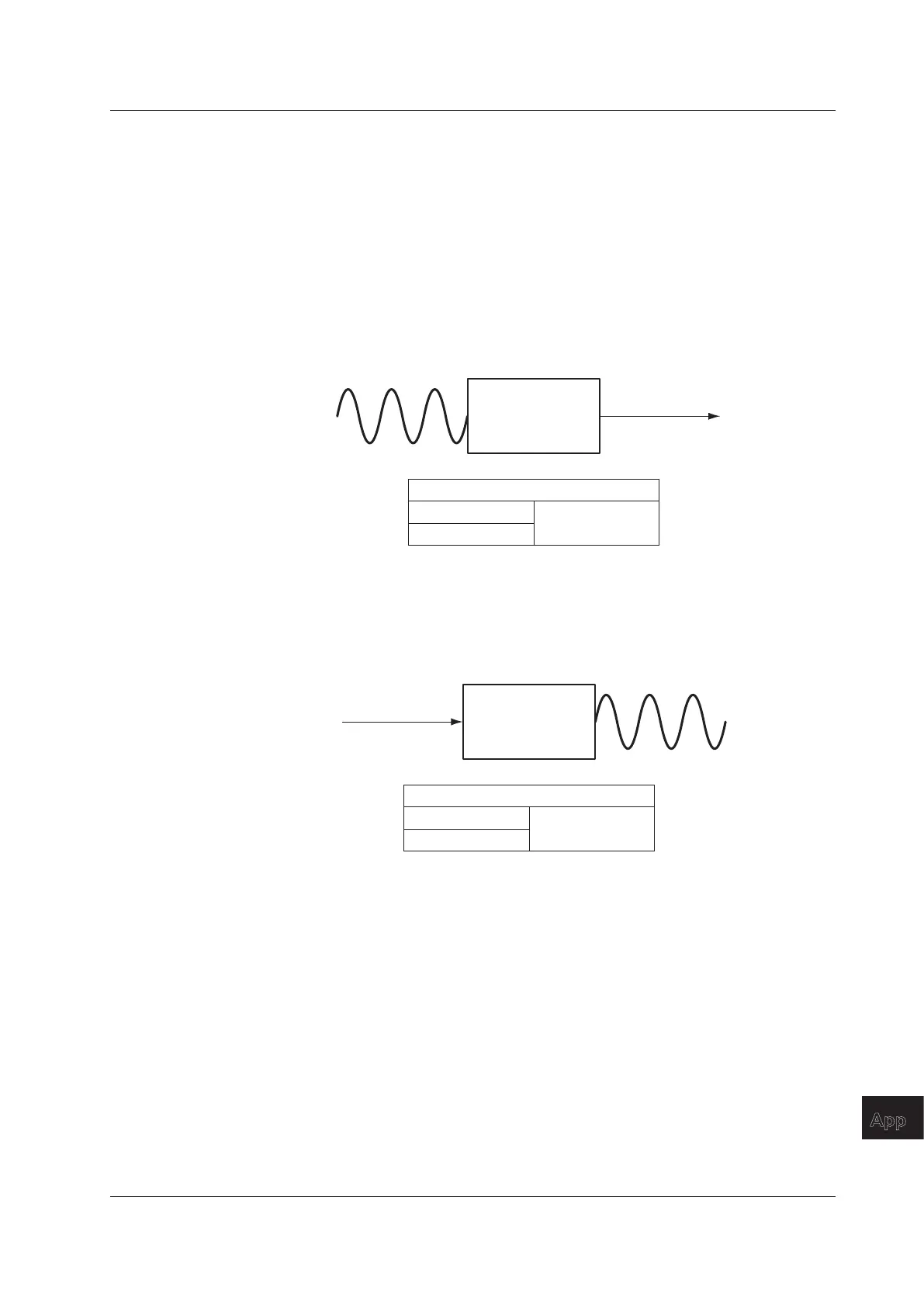
If a device that converts single-phase AC power to single-phase DC power is
measured with input elements 1 and 2, set the synchronization source of input
elements 1 and 2 to the voltage (or current) on the AC power end. In the example
shown in the figure below, set the synchronization source of input elements 1 and 2 to
U1 (or I1).
The measurement periods of input element 1 (input end) and i
nput element 2 (output
end) will match, and the power conversion efficiency of the device can be measured
more accurately.
Power transformer
Input: AC power U1 and I1 Output: DC power U2 and I2
U1 (or I1)
Input element 1
Input element 2
Synchronization Source Setup Example
Likewise, if a device that converts single-phase DC power to single-phase AC power
is measured with input elements 1 (DC end) and 2 (AC end), set the synchronization
source of input elements 1 and 2 to the voltage (or current) on the AC power end (input
element 2). In the example shown in the figure below, set the synchronization source
of input elements 1 and 2 to U2 (or I2).
Power transformer
Input: AC power U1 and I1 Output: AC power U2 and I2
U2 (or I2)
Input element 1
Input element 2
Synchronization Source Setup Example
• Power Transformer with Single-Phase DC Input and Three-Phase AC Output
If a device that converts single-phase DC power to three-phase AC power is
connected and measured as shown on the next page, set the synchronization source
of all input elements to the same signal: the voltage or current of element 2 or 3 on the
AC power end.
In this example, set the synchronization source of input eleme
nts 1, 2, and 3 to U2 (or
I2, U3, or I3). The measurement periods of the input signal and all output signals will
match, and the power conversion efficiency of the power conversion device can be
measured more accurately.
•
Single-phase DC power: Connect to input element 1.
• Three-phase AC power: Connect to input elements 2 and 3 using a three-phase,
three-wire system.
Appendix 5 Setting the Measurement Period

 Loading...


