I1(1)
I3(1)
I2(1)
F2(1)
F1(1),
FU1-I1
F3(1)
FU1-U3
U1(1)
I1(1)
I3(1)
U3(1)
I2(1)
U2(1)
FU1-U2
FU1-I3
FU1-I2
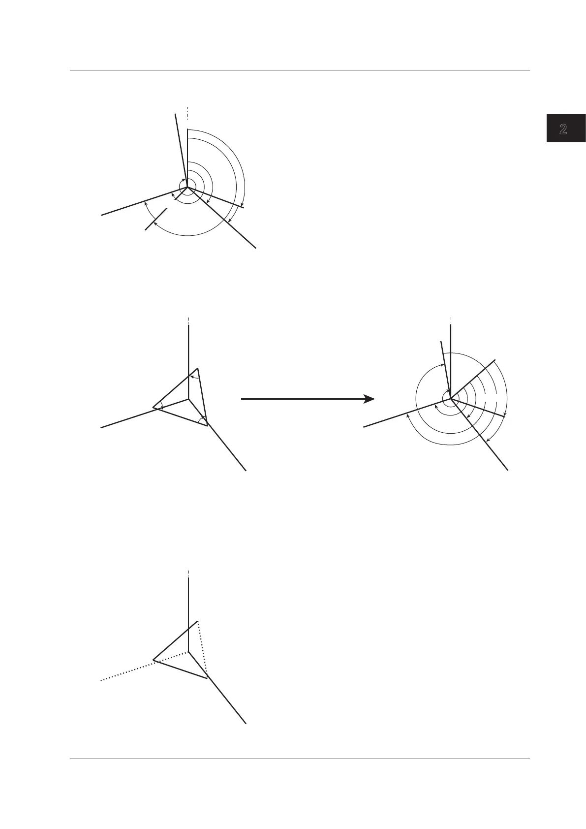
• Vector Display When the Wiring System Is 3P3W (3V3A; Three-voltage, three-current)
U1(1), U2(1), and U3(1) are line voltages. I1(1), I2(1), and I3(1) are line currents.
By moving the vectors U1(1),
U2(1), and U3(1) so that the
starting points of all vectors
are at the origin O, the phase
relationship can be observed
in the same fashion as the
3P4W system.
(The WT500 does not provide a
function for moving the vectors.)
O
U1(1)
I1(1)
I3(1)
U3(1)
I2(1)
U2(1)
• Vector Display When the Wiring System Is 3P3W (Three-phase, three-wire)
U1(1), U2(1), and U3(1) are line voltages. I1(1), I2(1), and I3(1) are line currents.
However, U3(1) and I3(1) are not actually measured for the 3P3W system.
The vectors are displayed through computation.
O
F2(1)
F1(1),
FU1-I1
F3(1)
FU1-U3
FU1-I2
U1(1)
I1(1)
I3(1)
U3(1)
I2(1)
U2(1)
FU1-U2
FU1-I3
• Vector Display When the Wiring System Is 3P4W (Three-phase, four-wire)
U1(1), U2(1), and U3(1) are phase voltages. I1(1), I2(1), and I3(1) are line currents.
U1(1)
U3(1)
U2(1)
FU1-U2
FU2-U3
FU3-U1
The phase difference between the line voltages
can be determined from the phase difference
measurement functions
FU1-U2 and FU1-U3.
FU1-U2 = Measurement function FU1-U2
FU2-U3=(FU1-U3) – (FU1-U2) – 180
FU3-U1=–(FU1-U3)

 Loading...


