3-11
IM 760201-01E
Before You Start Measuring
3
2
1
4
5
6
7
8
9
10
11
12
13
14
App
Index
Explanation
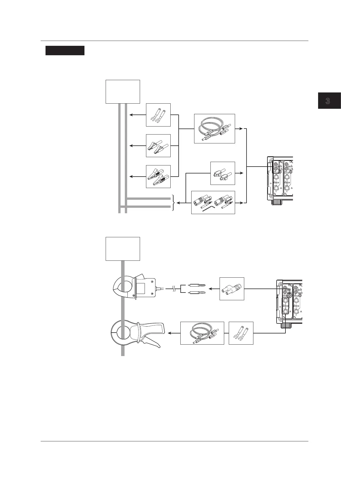
Wire the adapters that come with the WT500 or the adapters and various sensors that
are sold separately as shown below:
Wiring to the Voltage Input Terminal
Voltage under
measurement
758921
758922
758917
758923
758931
758929
WT500 voltage
input terminal
ELE MENT
VOLTAGE
1000V
MAX
EXT
CURR ENT
ALL TERMI NALS
1000 V MAX
TO
CAT
II
10V
MAX
1000V MAX
40A
MAX
ELE MENT
VOLTAGE
1000V
MAX
EXT
CURR ENT
ALL TERMI NAL
1000 V MAX TO
CAT
10V MAX
1000V MAX
40A
MAX
Use the separately sold clamp-on probes as follows:
Wiring to the Current Input Terminal
751550
(voltage output type)
* The current input terminal and EXT input terminal cannot be wired (used) simultaneously.
751552
(current output type)
758917 758921
758924
Current under
measurement
WT500 current
input terminal
Connecting a clamp-on probe
WT500 EXT
input terminal
ELE MENT
VOLTAGE
1000V
MAX
EXT
CURR ENT
ALL TERMI NALS
1000 V MAX
TO
CAT
II
10V
MAX
1000V MAX
40A
MAX
ELE MENT
VOLTAGE
1000V
MAX
EXT
CURR ENT
ALL TERMI NAL
1000 V MAX TO
CAT
10V MAX
1000V MAX
40A
MAX
3.6 Assembling the Adapter for the Voltage Input Terminal

 Loading...


