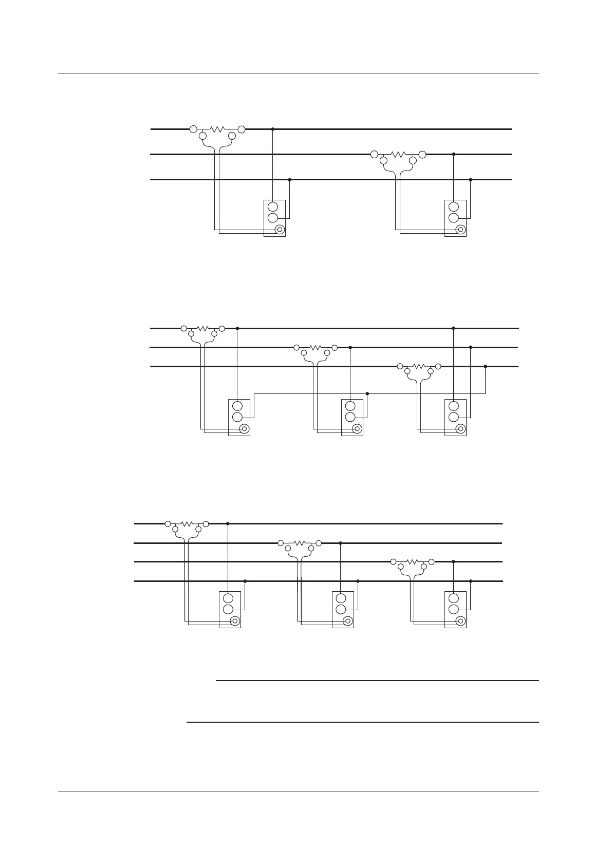
Wiring Example of a Three-Phase, Three-Wire System (3P3W) with a Shunt
Resistor
SOURCE LOAD
±I
OUT L
OUT H
±
±
±
I
OUT L
OUT H
R
S
T
External current sensor
input connector
(EXT)
Input terminal 1
U
External current sensor
input connector
(EXT)
Input terminal 2
U
Wiring Example of a Three-Phase, Three-Wire System with a Three-Voltage,
Three-Current Method (3P3W; 3V3A) and a Shunt Resistor
SOURCE
LOAD
±I
OUT L
OUT H
±
± ±
±
I
OUT L
OUT H
R
S
T
±
I
OUT L
OUT H
External current sensor
input connector
(EXT)
Input
terminal 1
U
External current sensor
input connector
(EXT)
Input
terminal 2
U
External current sensor
input connector
(EXT)
Input
terminal 3
U
Wiring Example of a Three-Phase, Four-Wire System (3P3W) with a Shunt
Resistor
SOURCE LOAD
±I
OUT LOUT H
±
± ± ±
I
OUT LOUT H
R
S
T
N
±
I
OUT LOUT H
External current sensor
input connector
(EXT)
Input
terminal 1
U
External current sensor
input connector
(EXT)
Input
terminal 2
U
External current sensor
input connector
(EXT)
Input
terminal 3
U
Note
For details about the relationship between the wiring system and how measured and computed
values are determined, see appendix 1, “Symbols and Determination of Measurement
Functions.”
3.10 Wiring the Circuit That You Will Measure with a Current Sensor

 Loading...


