4-3
IM 760201-01E
Measurement Conditions
3
2
1
4
5
6
7
8
9
10
11
12
13
14
App
Index
Explanation
Wiring System
• There are five wiring systems available on the WT500. The selectable wiring systems
vary depending on the number of elements installed in the WT500.
(1) 1P2W
, single-phase, two-wire; (2) 1P3W, single-phase, three-wire; (3) 3P3W,
three-phase, three-wire; (4) 3P4W, three-phase, four-wire; and (5) 3V3A, three-
voltage, three-current.
•
The wiring system determines how input elements are assignment to wiring unit
Σ
and how
Σ
functions (such as voltage, current, active power, apparent power, reactive
power, power factor, and phase difference) are determined. For details about the
relationship between the wiring system and how
Σ
functions are determined, see
Appendix 1.
•
The following table shows the relationship between the number of installed input
elements, the selectable wiring systems, and the assignment of input elements to
wiring unit
Σ
.
Number of installed input elements
Wiring system Pattern 1
1
1P2W
Number of installed input elements
Wiring system Pattern 1
Wiring system Pattern 2
1
1P2W
2
1P2W
1P3W:Σ or 3P3W:Σ
Number of installed input elements
Wiring system Pattern 1
Wiring system Pattern 2
Wiring system Pattern 3
Wiring system Pattern 4
1
1P2W
2
1P2W
3
1P2W
1P2W
1P2W
1P3W:Σ or 3P3W:Σ
1P3W:Σ or 3P3W:Σ
3P4W:Σ or 3P3W (3V3A):Σ
Note
• Select the wiring system to match the actual wiring of the circuit under measurement. The
method in which the
Σ
functions are determined varies depending on the wiring system. If
the selected wiring system does not match the wiring of the actual circuit, measurements
and computation will not be correct.
•
For details about the relationship between the wiring system and how
Σ
functions are
determined, see Appendix 1.
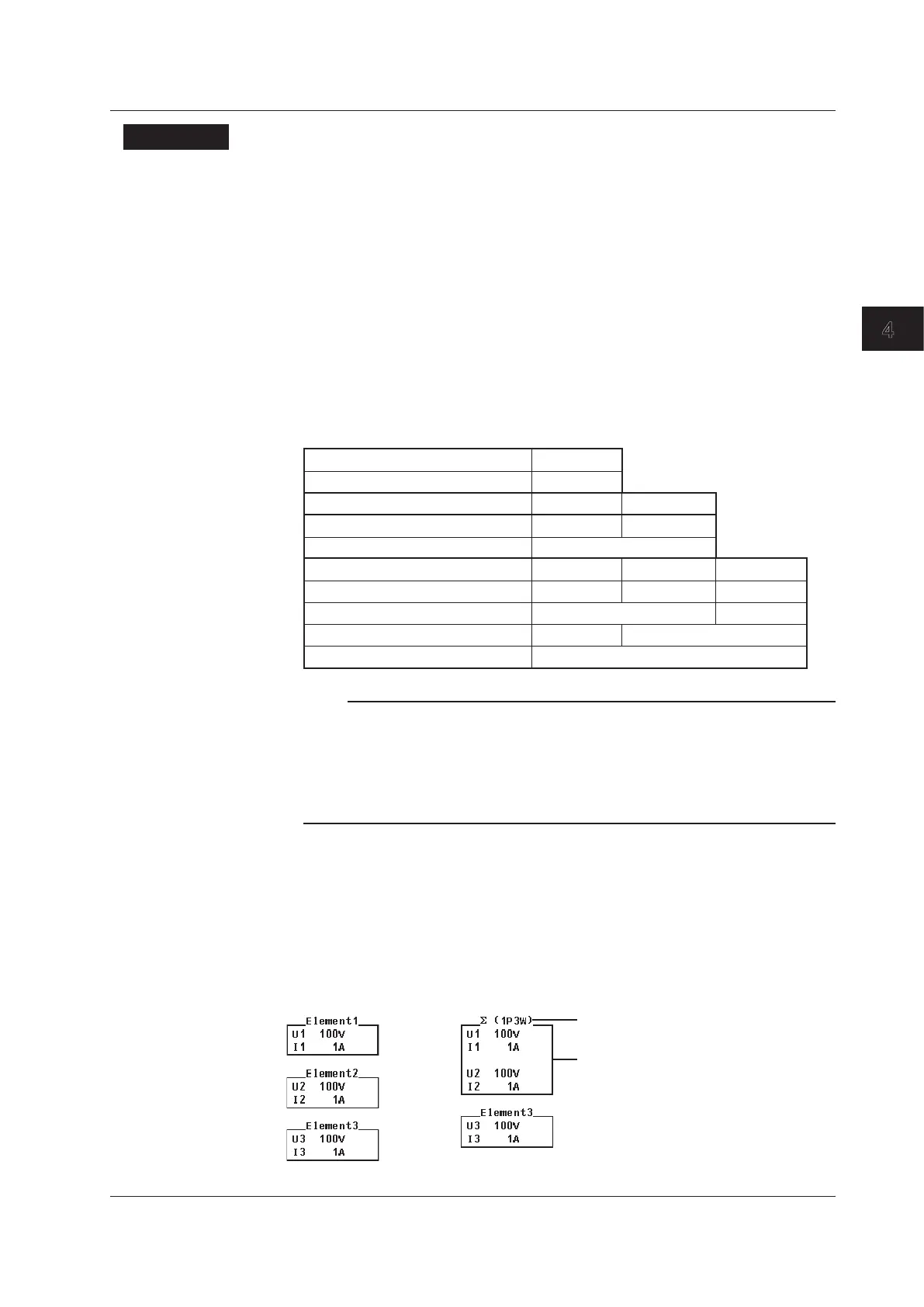
Wiring System Display
The wiring system configuration is displayed on the right side of the screen. Because it is
displayed behind the menu, to view it, you need to press the ESC key to hide the menu.
The figure below shows wiring system display examples for a model with three input
elements installed.
When elements 1 to 3 are
set to single-phase,
two-wire system
When element 1 and 2 are set to single-phase,
three-wire system, and element 3 is set to single-phase,
two-wire system
Wiring unit and system
The elements that make up the
wiring unit are contained in the frame.
4.2 Selecting a Wiring System

 Loading...


