STARTUP
Carl Zeiss Mounting the Standard Components Axio Scope.A1
36 M60-2-0007 e 05/08
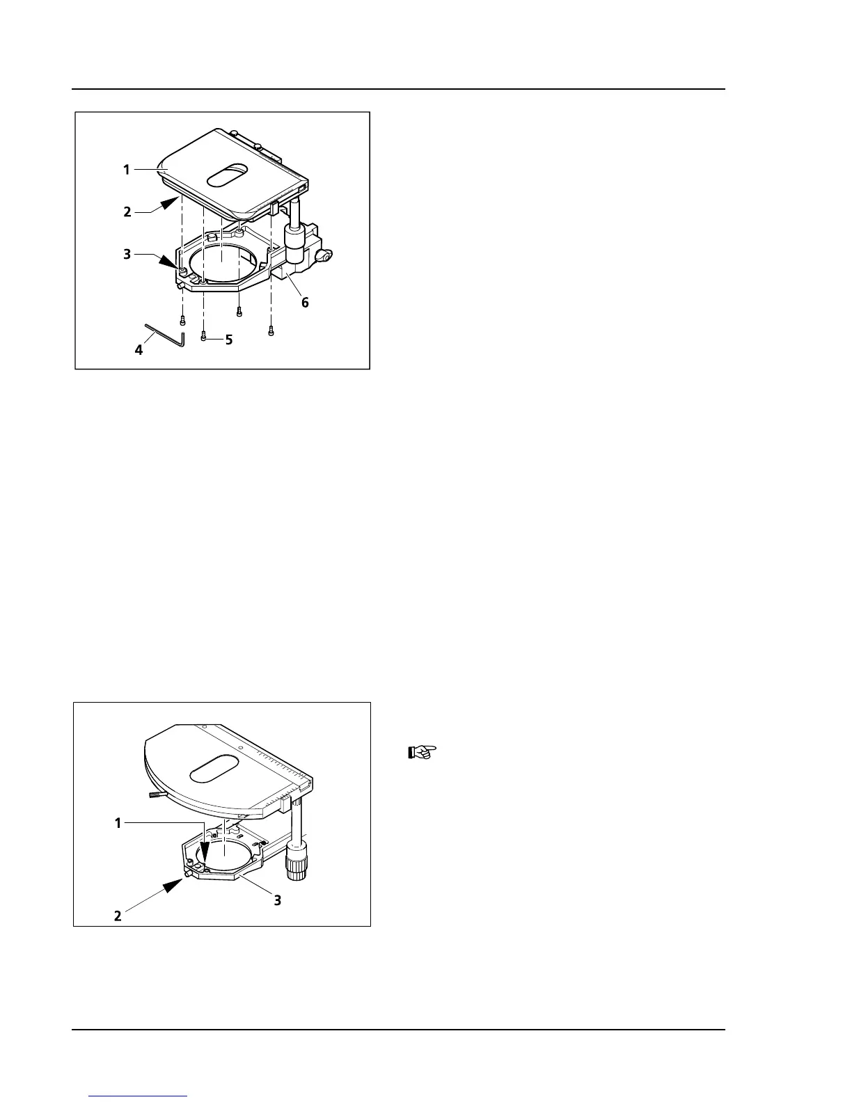
3.1.8 Mounting the Mechanical Stage
Depending on the type, the mechanical stages can
either be stable or they can be rotated and
centered. The shift range is 75 mm in X-direction
and 50 mm in Y-direction. There are stable stages
available with the drive to the right or the lefts.
The rotatable mechanical stage has the drive on its
right.
To assemble / disassemble a stage, remove the
stage carrier, then mount the stage carrier with the
mounted stage onto the stand again.
(1) Stable mechanical stage 75x50 R
a) How to remove the stage
• Remove the four mounting screws (
325H325HFig. 3-10/5)
on the stage carrier (
326H326HFig. 3-10/6) with the aid of
the ball head screwdriver SW 3 (
327H327HFig. 3-10/4).
• Pull off the stage (
328H328HFig. 3-10/1) from the stage
carrier. This is easier if you turn the stage and its
carrier over.
b) How to mount the stage
• Put the stage (
329H329HFig. 3-10/1) onto the stage carrier (330H330HFig. 3-10/6) so that the threaded holes in the bottom
of the stage (
331H331HFig. 3-10/2) are on top of the corresponding holes in the stage carrier (332H332HFig. 3-10/3).
• Insert the four mounting screws (
333H333HFig. 3-10/5) from below through the holes in the stage carrier and
screw them into the bottom of the stage.
• Align the stage in the XY-direction before tightening the screws.
(2) Rotatable mechanical stage 75x50/240° R
Rotatable stages can only be used
together with the stage carrier for
rotatable stages (430710-9010-000).
a) How to remove the stage
• Loosen the screw caps (
334H334HFig. 3-11/2) of the
spring box with approx. 3 turns.
• Press the stage forward against the spring pin
(
335H335HFig. 3-11/1), lift the backside off the stage
carrier (
336H336HFig. 3-11/3) and remove it by lifting it
upward.
• Tighten the screw caps (
337H337HFig. 3-11/2).
Fig. 3-10 Changing the stable mechanical
stage
Fig. 3-11 Changing the rotatable mechanical
stage