OPERATION
Axio Scope.A1 Illumination and Contrasting Method Carl Zeiss
M60-2-0007 e 05/08 81
(3) Adjusting the microscope
• Adjust the microscope as described in chapter
650H650H4.1.1 (3) for transmitted light/bright-field. Make sure
the eye distance is adjusted correctly on the binocular tube (see chapter
651H651H3.5.1).
• Center the rotary stage Pol (
652H652HFig. 4-7/1).
• Swing the polarizer (
653H653HFig. 4-7/3) in the beam path and position it to 0° if you are using a rotatable
polarizer.
• Swing the analyzer module on the reflector turret in (
654H654HFig. 4-7/2) (or slide the analyzer slider into the
intermediate plate). Because of the crossed polarizers the field of view now appears dark.
• Place the adjustment sample Pol on the microscope stage and turn until the sample appears dark.
• Switch off the analyzer and align the graticule along the split cracks of the object.
• Now switch the analyzer back on and remove the sample. The forward direction of polarizer and
analyzer are now parallel to the graticule (Polarizer EW, Analyzer NS).
• Turn the rotary stage Pol with the sample, e.g. a synthetic fiber, so that the sample reaches maximal
darkness. The fiber is now parallel to one of the two graticule directions. If the deflection is significant
(5° and more) you will need to use a polarization microscope.
Do not change the eyepiece distance on the binocular tube any further in order to avoid
shifting the angular position of the graticule to the fiber.
• Now turn the stage by approx. 45° until the
longitudinal axis of the fiber is pointing in NE-
SW direction (
655H655HFig. 4-9). The sample now shows
the strongest brightness (diagonal position). The
sample can have any color in this position.
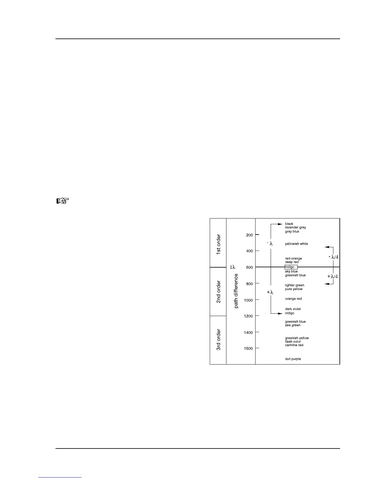
• Slide in the compensator λ.
Like the sample, the compensator λ is a
birefringent object, but it has a defined path
difference of 550 nm and a maximum oscillation
direction n
γ
pointing strongly to NE-SW.
When the compensator λ is put in, the sample
changes its color depending on its orientation (NE-
SW or NW-SE).
The changes in color are based on optical
interference. It is necessary to compare the
interference colors (phase differences) in both
diagonal positions (NE-SW and NW-SE).
Fig. 4-9 Diagram of the color tables
according to Michel-Lévy