STARTUP
Axio Scope.A1 Mounting Optional Components Carl Zeiss
M60-2-0007 e 05/08 61
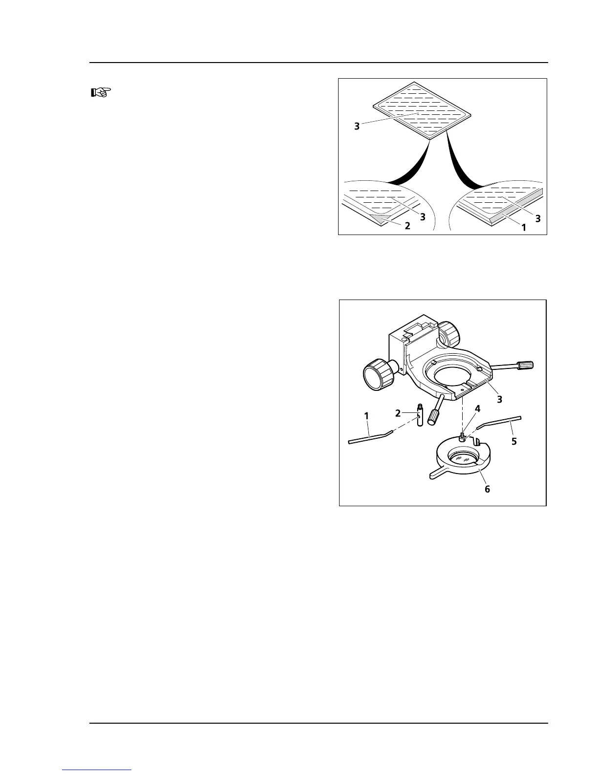
The reflecting (coated) side (
550H550HFig. 3-46/3)
of the color splitter has a tapered edge
(
551H551HFig. 3-46/1) or corner (552H552HFig. 3-46/2).
• Put the excitation part of the module
(
553H553HFig. 3-45/1) on the emission part (554H554HFig. 3-45/4)
– holding fixtures (
555H555HFig. 3-45/5b) and eyelets
(
556H556HFig. 3-45/5a) latch together. Hold both parts
together and turn them back into mounting
position.
• Replace the slit screws and tighten them.
• Last, stick the sticker with the name of the filter
combination on the side of the module.
3.4.7 Mounting the Polarizer D or the
Filter Holder
• For an easy assembly, remove the condenser
carrier (
557H557HFig. 3-47/3) fully, with the stage carrier.
• If necessary, unscrew stop bolt and bracket bolt
with overview fixture from the condenser
carrier.
• Hold the polarizer or filter holder (
558H558HFig. 3-47/6)
parallel to the bottom of the condenser carrier
(
559H559HFig. 3-47/3) and screw the bracket bolt
(
560H560HFig. 3-47/4) of the polarizer (561H561HFig. 3-47/6) with
the angled adjustment lever (
562H562HFig. 3-47/5) in to
the front threaded opening at the left below
the condenser carrier (
563H563HFig. 3-47/3) until it stops.
• Screw the stop bolt (
564H564HFig. 3-47/2) with the
adjustment lever (
565H565HFig. 3-47/1) to the stop into
the back threaded opening of the condenser
carrier (
566H566HFig. 3-47/3).
Proceed analogically when mounting the other components listed in the Systems Overview.
Fig. 3-46 Labeling the color splitter
Fig. 3-47 Mounting the polarizer D