STARTUP
Axio Scope.A1 Mounting the Standard Components Carl Zeiss
M60-2-0007 e 05/08 37
b) How to mount the stage
• Loosen the screw caps (
338H338HFig. 3-11/2) of the spring box with approx. 3 turns.
• Put the stage with the dovetail ring notch onto the spring pin (
339H339HFig. 3-11/1).
• Press the stage forward against the spring pin and lower its back into the stage carrier (
340H340HFig. 3-11/3).
• Tighten the screw caps (
341H341HFig. 3-11/2).
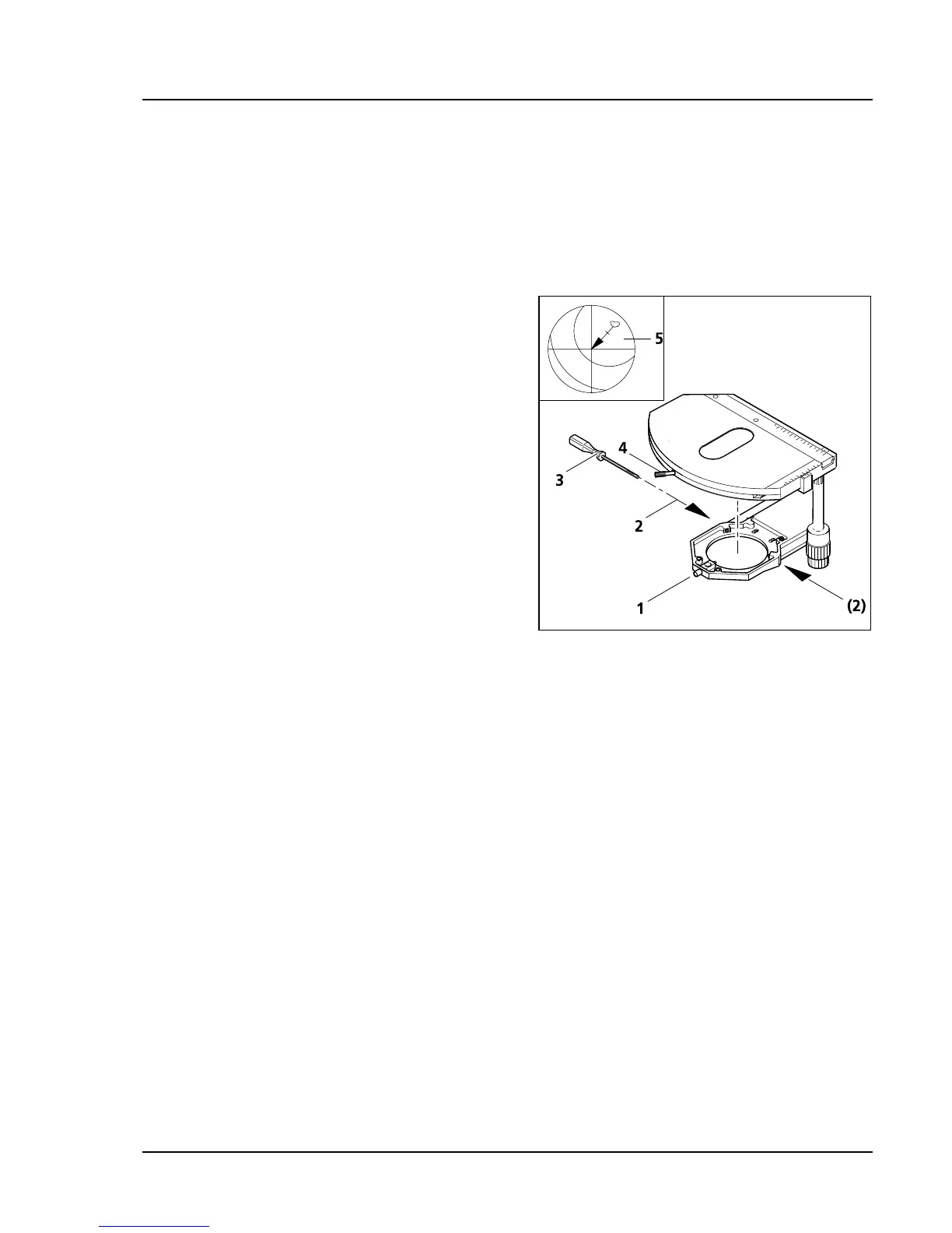
c) How to center the stage
When using objectives with a high magnification,
only one chosen objective can be centered exactly
at a time.
All stages are delivered precentered, i.e. when the
stage is turned, the detail of the object in the focus
remains in the center of the image. If the detail
shifts out of the center when the stage is turned
(
342H342HFig. 3-12/5), then it becomes necessary to recenter
the stage.
• Loosen the clamping screws of the stage (
343H343HFig.
3-12/4) and the screw caps of the stage carriers
(
344H344HFig. 3-12/1).
• Determine the maximal shift of the object (
345H345HFig.
3-12/5, arrow point) to the cross line in the
eyepiece by turning the stage.
• Shift the object detail towards the center of the
cross line by turning the two centering screws
on the stage carrier (
346H346HFig. 3-12/2) each with an
hexagon head screwdriver SW 1.5 (
347H347HFig. 3-12/3)
half the length of the arrow. Repeat the
procedure if the object detail shifts out of the
center again when turning the stage.
• After finishing the centering procedure tighten the screw caps (
348H348HFig. 3-12/1) again.
The stage can be turned by 240° within a shifting range of y ≤ 27 mm. No turning of the stage is possible
outside of this range.
(3) Adjusting the drive length on the ergonomics
An axial shift of the gear knobs by a maximum of 15 mm can enhance the drive length of the X and Y
shift on the mechanical stages with ergonomic drive.
Fig. 3-12 Centering the rotatable mechanical
stage