STARTUP
Carl Zeiss Mounting Optional Components Axio Scope.A1
58 M60-2-0007 e 05/08
3.4.4 Mounting the Magnification
Changer
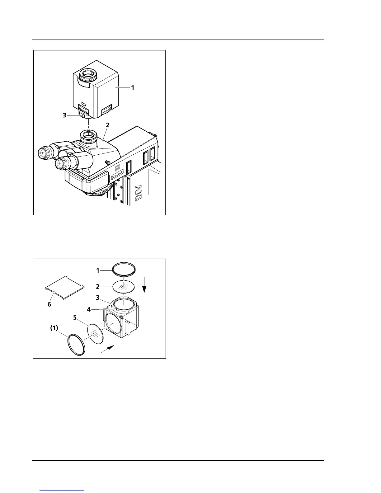
• If necessary, remove camera with adapter (or
dust protection cover) from the camera port of
the photo tube (
521H521HFig. 3-41/2).
• Mount the magnification changer (
522H522HFig. 3-41/1)
onto the camera port, adjust it and fixate it with
the retainer nut (
523H523HFig. 3-41/3).
• Mount the camera with the appropriate adapter
onto the camera port of the magnification
changer.
The scanning power for changing the
remagnification modules can be adjusted with the
screw with a white circle on the bottom of the
housing.
3.4.5 Changing the Filters in the
Reflector Module FL P&C
• Remove the reflector module FL P&C
(
524H524HFig. 3-42/3) from the reflector turret and put it
aside (see also chapter
525H525H3.1.6).
• Unscrew the adapter ring (
526H526HFig. 3-42/1) with the
mounting plate included with the tools
(
527H527HFig. 3-42/6).
• Turn over the reflector module and let the filter
(
528H528HFig. 3-42/2 or 5) drop onto a soft surface.
• The emission filter is inserted in
529H529HFig. 3-42/2, the
excitation filter in
530H530HFig. 3-42/5. Then fixate with
the adapter rings (
531H531HFig. 3-42/1).
Emission and excitation filters can have a name
and an arrow in the girth. The arrow indicates
which way the filter must be mounted on the
reflector module and should always point inward
(see arrows in
532H532HFig. 3-42).
In order to minimize the image offset in multiple fluorescence images, the emission filter may have
another mark to factor in the point angle.
Fig. 3-41 Mounting the magnification
changer
Fig. 3-42 Changing the filters in the reflector
module FL P&C