STARTUP
Carl Zeiss Mounting the Standard Components Axio Scope.A1
38 M60-2-0007 e 05/08
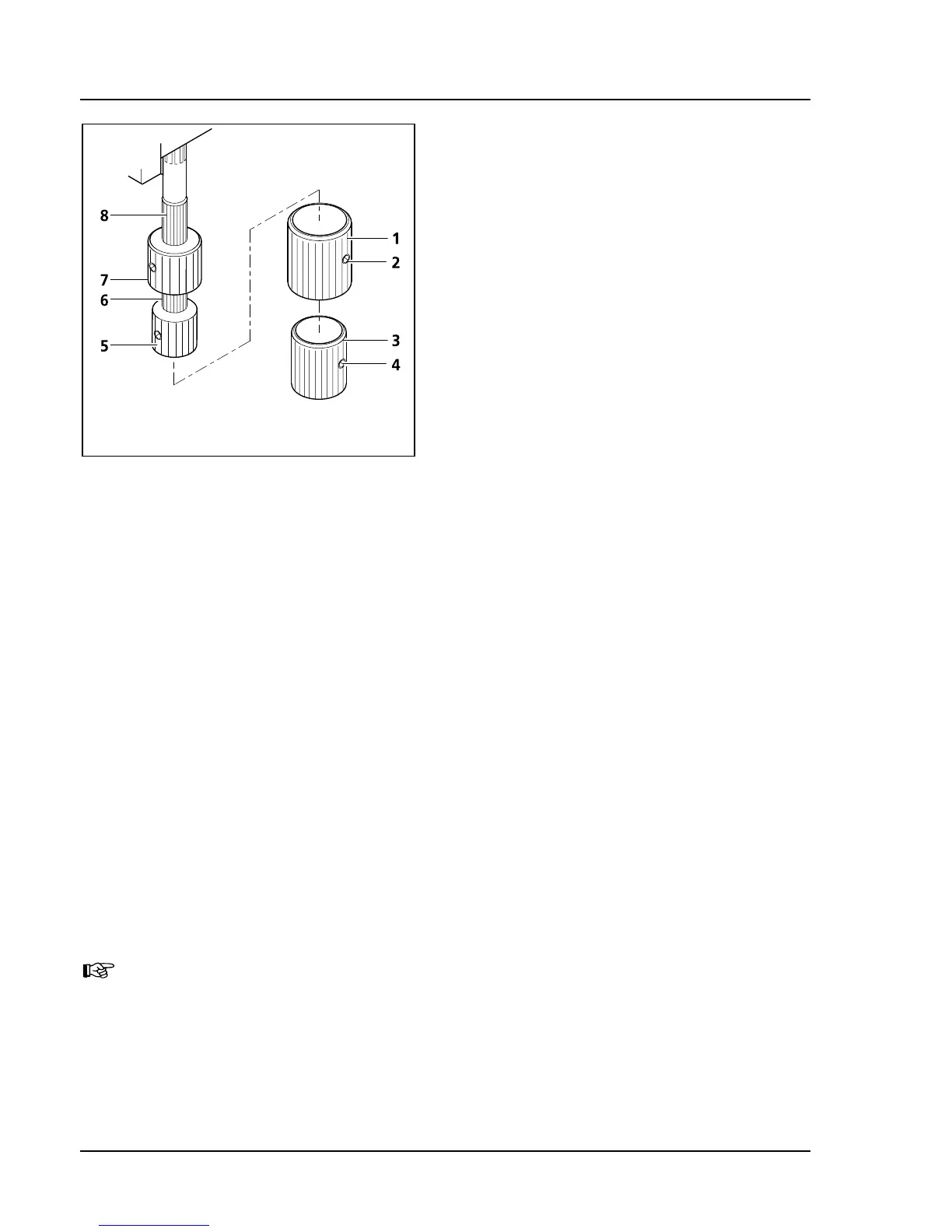
(4) Removing and mounting the additional
sleeves
Both gear knobs for the stages with the order no.
432035-9030-000, 432035-9040-000 and
432035-9050-000 are equipped with additional
sleeves for an even more sensitive adjustment of
the object position. These sleeves can be removed
in those cases when it is important to shift the
object more quickly.
• Loosen both clamping screws (
349H349HFig. 3-13/4) on
the lower additional sleeve (
350H350HFig. 3-13/3) and
remove them by pulling them down. Then
loosen both clamping screws (
351H351HFig. 3-13/2) on
the upper additional sleeves (
352H352HFig. 3-13/1) and
remove them by pulling them down as well.
• Mount the additional sleeves again on the gear
knobs by proceeding in the reverse order.
Tighten the clamping screws when you are
done.
(5) Adjusting the friction (smoothness of operation) on both gear knobs of the ergonomics
The smoothness of ergonomics operation is factory-adjusted to a mid degree. The operator can change
the friction as follows:
a) How to adjust the X-direction
• Remove the additional sleeves (
353H353HFig. 3-13/1 and 3) from the gear knobs by loosening the clamping
screws.
• Shift the X-gear knob (
354H354HFig. 3-13/5) downward and the Y-gear knob (355H355HFig. 3-13/7) upward.
• Hold the X-gear knob (
356H356HFig. 3-13/5) and turn the light colored knurled ring above it (357H357HFig. 3-13/6) to the
right (increased smoothness) or left (decreased smoothness) until you reach the desired degree.
b) How to adjust the Y-direction
• Hold the Y-gear knob (
358H358HFig. 3-13/7) and turn the light colored knurled sleeve above it (359H359HFig. 3-13/8) to
the right (increased smoothness) or the left (decreased smoothness) until you reach the desired
degree.
• Replace the additional sleeves and tighten the clamping screws.
Enhance the life span of the stage by regularly removing the particles abraded from the object
carriers. Avoid getting any particles in the mechanical guiding system of the X-adjustment.
Fig. 3-13 Adjusting ergonometric drive