STARTUP
Axio Scope.A1 Mounting the Standard Components Carl Zeiss
M60-2-0007 e 05/08 39
3.1.9 Mechanical Stages with Friction Adjustment
Drive length and friction for the X- and Y-adjustment can be adjusted individually on the standard
mechanical stage (432035-9000-000) and the mechanical stage 432035-9070-000.
(1) Adjusting the drive length on the stage
drive
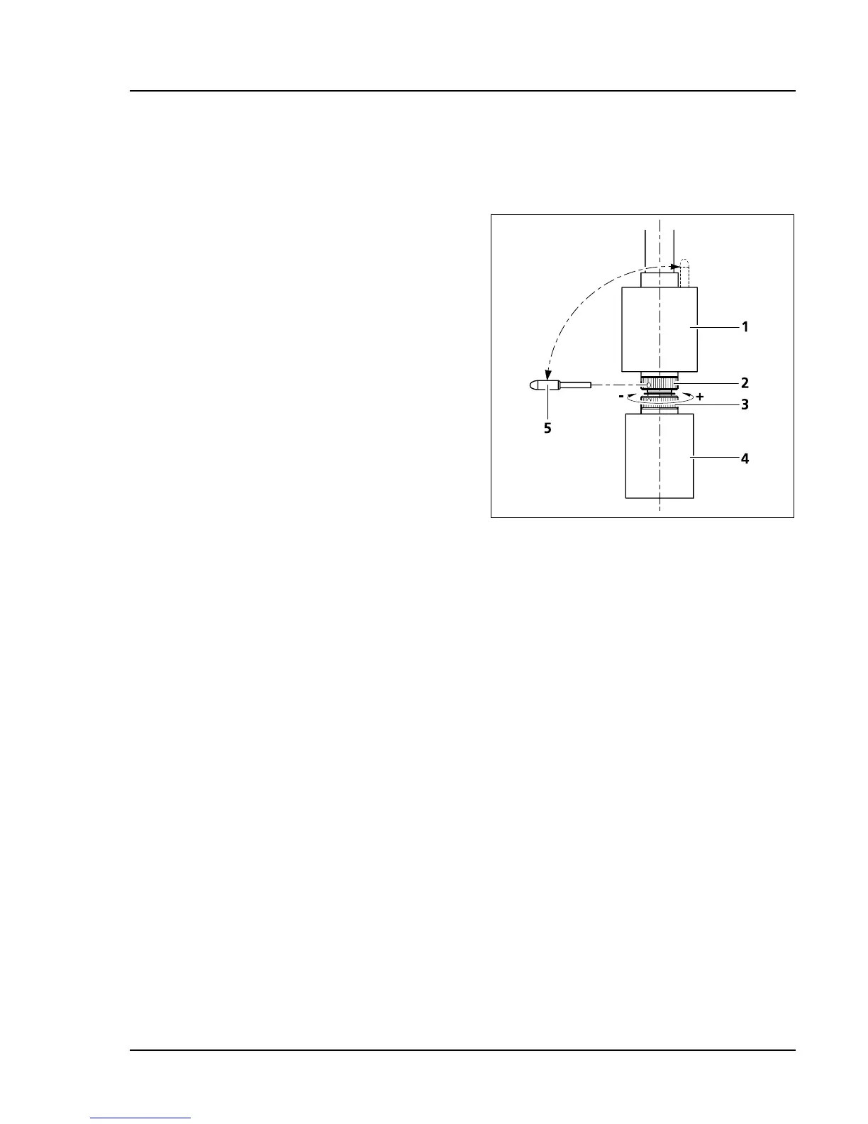
The drive length of the X- and Y-drive can be
adjusted by an axial shift of the gear knob
(
360H360HFig. 3-14/4 and 1) within a range of approx.
15 mm.
(2) Adjusting the frictional momentum of the
gear knobs for the X-/Y-adjustment of the
mechanical stage
The friction momentum of the gear knobs is
factory-adjusted to a mid degree which can be
changed as follows if necessary:
a) X-drive
• Slide the gear knob for the X-adjustment (
361H361HFig.
3-14/4) all the way down.
• Take the enclosed adjustment pin (
362H362HFig. 3-14/5)
out of the gear knob for the Y-adjustment (
363H363HFig.
3-14/1) and stick it into one of the holes on the
lower hole nut (
364H364HFig. 3-14/3).
• Hold the gear knob for the X- adjustment (
365H365HFig. 3-14/4) and turn the hole nut with the adjustment pin
clockwise (smaller friction momentum: –) or counter clockwise (larger friction momentum: +) until you
reach the desired friction degree (see
366H366HFig. 3-14).
• The adjustment should not be more than one rotation.
b) Y-drive
• Slide the gear knob for the Y-adjustment (
367H367HFig. 3-14/1) all the way up.
• Stick the enclosed adjustment pin (
368H368HFig. 3-14/5) into the hole on the upper hole nut (369H369HFig. 3-14/2).
• Hold the gear knob for the Y-adjustment (
370H370HFig. 3-14/1) and turn the hole nut with the adjustment pin
clockwise (smaller friction momentum: –) or counter clockwise (larger friction momentum: +) until you
reach the desired friction degree.
• The adjustment should not be more than one rotation.
• Replace the adjustment pin in the gear knob for the Y-adjustment (
371H371HFig. 3-14/1).
Fig. 3-14 Adjusting the frictional momentum