STARTUP
Axio Scope.A1 Mounting the Standard Components Carl Zeiss
M60-2-0007 e 05/08 51
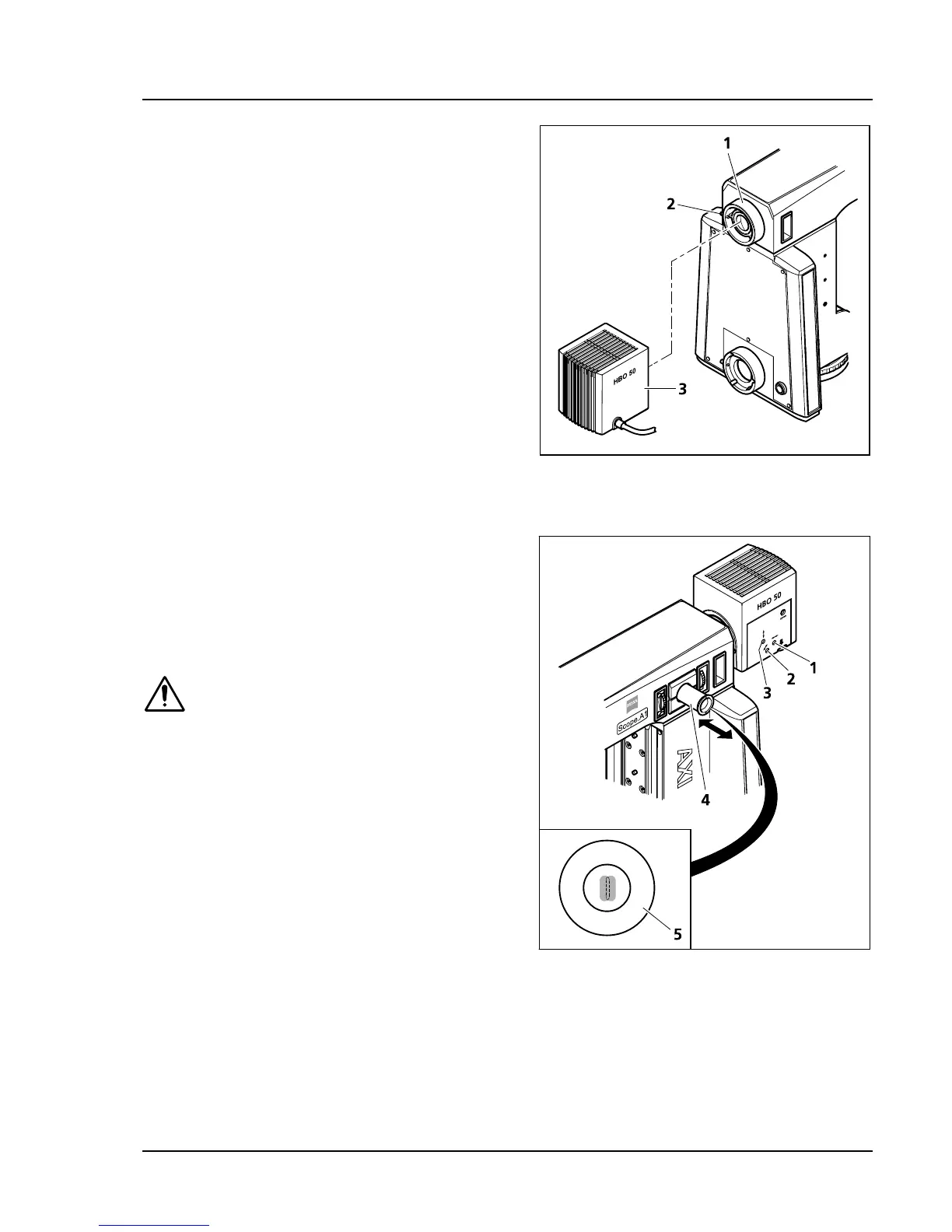
3.1.17.2 Mounting HBO 50 illuminator
• Mount HBO 50 illuminator (
464H464HFig. 3-29/3) on the
connection piece (
465H465HFig. 3-29/1) of the upper
stand part, align it and tighten the clamping
screw (
466H466HFig. 3-29/2).
• Plug the HBO 50 connection cord into the
transformer. Then plug the transformer into an
electrical outlet.
• Switch the HBO 50 illuminator on and off by
pressing the power switch on the front of the
power supply unit. The lamp ignites
automatically when switched on.
3.1.17.3 Adjusting the HBO 50 illuminator
If the Axio Scope.A1 is equipped with an
adjustment aid (to be ordered separately), the
HBO 50 can remain on the fluorescence reflected
light illuminator when adjusting the burner.
• Switch on the illuminator after mounting it fully
on the transformer. The burner ignites
automatically.
If the images of the light arc and the
reflection overlap, the burner’s thermal
load can increase. This may shorten its
lifespan.
• Make sure that the FL attenuator its set to
100 % transmission.
• Pull out the adjustment aid (
467H467HFig. 3-30/4). The
adjusting aid’s display panel (
468H468HFig. 3-30/5) shows
the burner’s light arc (in a lighter color) and its
reflection (slightly darker).
• With the aid of the adjustment screw
(
469H469HFig. 3-30/1) adjust the burner axially to the
mirror so that both light arcs appear the same
size in the display panel of the adjustment aid
(see
470H470HFig. 3-30/5).
• With the aid of the adjustment screws center the light arc and its reflection vertically (
471H471HFig. 3-30/3) and
horizontally (
472H472HFig. 3-30/2) and position those in a parallel line within the adjustment circle of the display
panel (
473H473HFig. 3-30/5). Light arc and reflection should not overlap.
• Slide the adjustment aid back in after finishing the adjustment procedure.
Fig. 3-29 Mounting the HBO 50
Fig. 3-30 Adjusting the HBO 50