OPERATION
Carl Zeiss Illumination and Contrasting Method Axio Scope.A1
88 M60-2-0007 e 05/08
4.1.10 Adjusting Reflected Light TIC
(1) Application
The reflected light TIC method (Micro-interferometry; TIC = Total Interference Contrast in the circular
polarized light) is used in imaging and measuring object structures which are on hand in different
azimuths.
(2) Instrumentation
− Axio Scope.A1 with adjusted halogen lamp
HAL 100 mounted on the reflected light
barrel
− Objectives EC Epiplan-Neofluar, Epiplan with
additional label "DIC" or "Pol"
− Compensator compartment 6x20
− TIC slider 6x20 with appropriate reflector
module C DIC P&C
(3) Adjusting reflected light TIC
• Put down the sample (e.g. a stepped object)
and adjust the microscope for reflected
light/bright-field as described in chapter
678H678H4.1.7.
• Swing reflector module C DIC P&C on the
reflector turret in the beam path.
• Slide TIC slider 6x20 in the compensator compartment 6x20 (
679H679HFig. 4-12/1). You will see chromatic
interference stripes in the field of view. Using the control knob (
680H680HFig. 4-13/2) of the TIC slider, move the
black interference stripe by sight to the middle of the field of view.
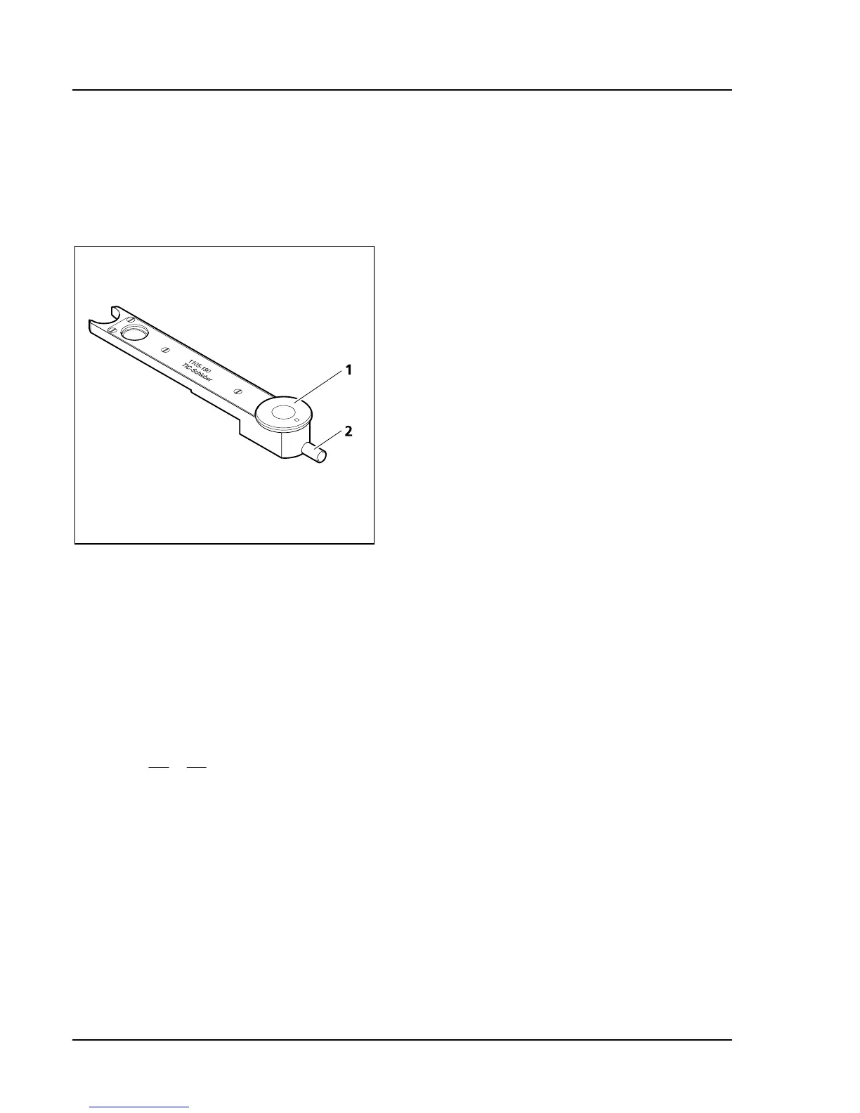
• In order to choose the structure to be measured, turn the knob (
681H681HFig. 4-13/1) on the TIC slider until the
interference stripes are vertical to the direction in which the object is broken down (see
682H682HFig. 4-14). The
interference stripes can be shifted with the aid of the control button (
683H683HFig. 4-13/2).
The step-height d is then determined with the following formula:
a2
b
2
n
d
λ
=
Δ
=
With: d = step-height in nm
n = refractive index of the environment, mostly air (n = 1)
Δ = phase difference
a = distance between interference stripes
b = offset of the interference stripes along the step
λ = wave length of the illumination in nm
Fig. 4-13 TIC slider 6x20