STARTUP
Axio Scope.A1 Mounting Optional Components Carl Zeiss
M60-2-0007 e 05/08 59
When mounting the appropriate emission filter
into the according reflector module, the mark
should be aligned with the orientation groove
(
533H533HFig. 3-42/4). This guarantees that the point angle
in the reflector modules acts equally and
compensates or minimizes the image offset –
already low in Zeiss filter sets – even further.
When mounting a filter without any orientation
marks (arrow), we advise to proceed like this:
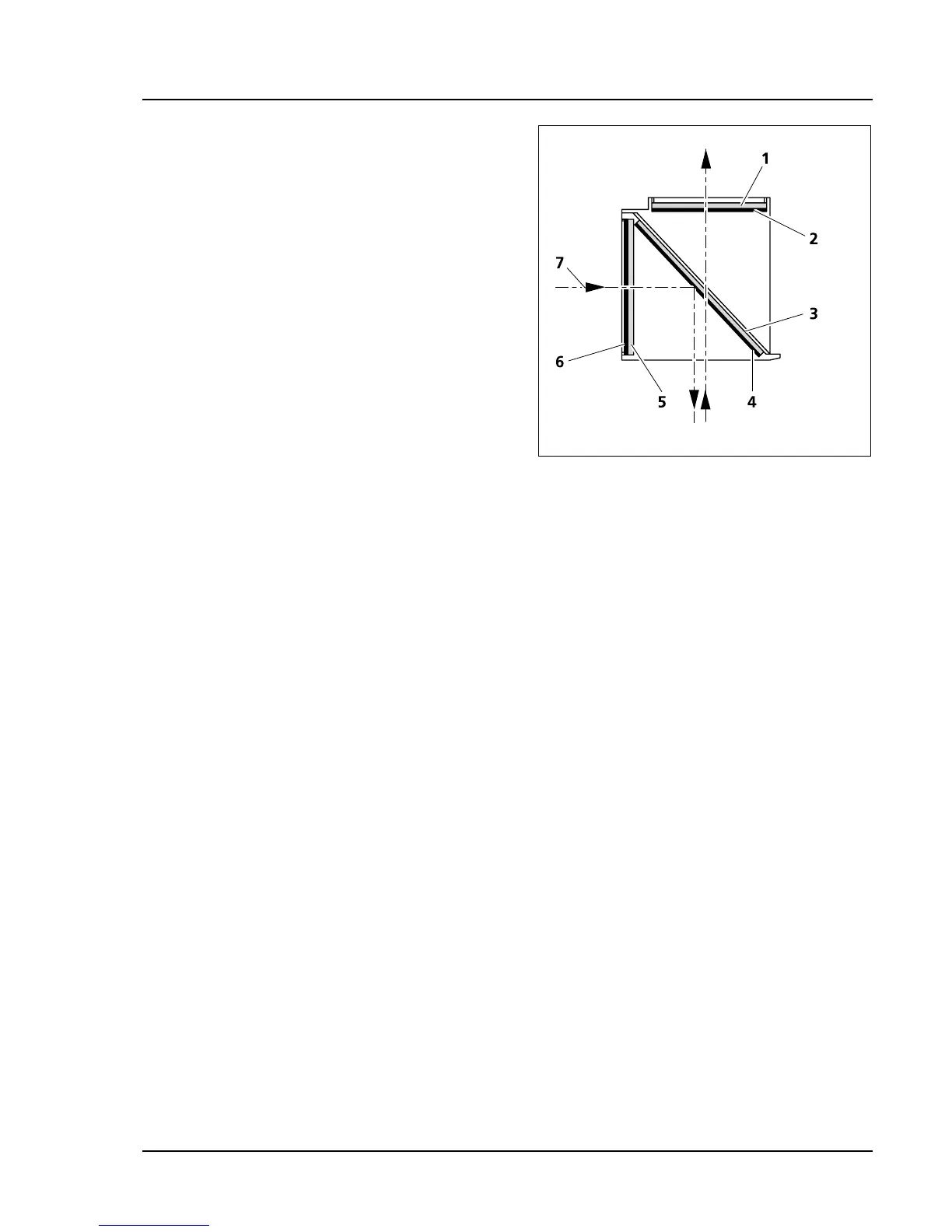
Filters with reflecting, di-electrical coating are
mounted so that the reflecting coating (
534H534HFig.
3-43/6) faces outward (in relation to the reflector
module) in excitation filters (
535H535HFig. 3-43/5) and
inward in emission filters (
536H536HFig. 3-43/2).
The reflecting coating (
537H537HFig. 3-43/4) of the color
splitter (
538H538HFig. 3-43/3) faces down when mounted.
The arrows (
539H539HFig. 3-43/7) mark the path of the
illumination beam or the imaging beam.
Fig. 3-43 Mounting the filters and the color
splitter