4 Cabling the AC 800F
4-46
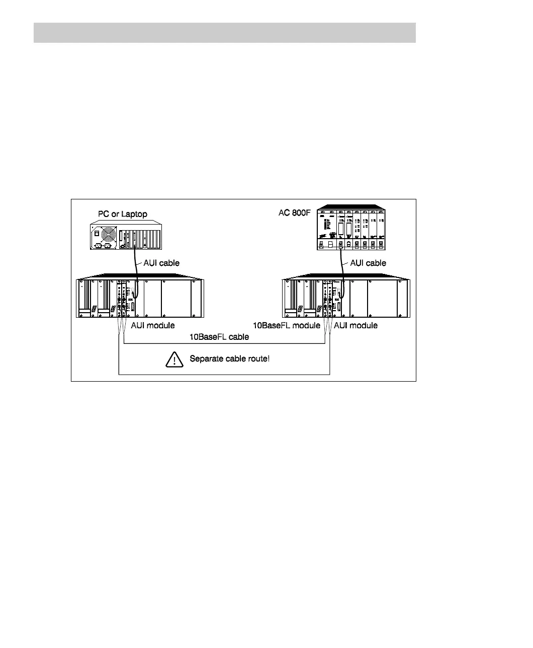
Example for two nodes:
2 network concentrators, 10/19 slots, with redundant power supply
4 10BaseFL modules
2 AUI modules
2 AUI cables
2 10BaseFL cables
1 clip TV 83xF
Cable the components as shown in Fig. 4-25.
Fig. 4-25 Redundant 10BaseFL cabling, case 1
Configure one of the two 10BaseFL modules for redundant operation by setting the
jumper accordingly. Set the 10BaseFL modules to the appropriate transmission
power, depending on the distance. Observe the operating instructions for the
individual components and the information given in Section 4.2.10.2.
The fiber optic cable link between the two network concentrators is redundant. The
cables should be laid on different routes to reduce the risk that both cables are
damaged at the same time. If one of the two links fails, the network concentrators
automatically switch over to the redundant link without interrupting operation. The
10BaseFL modules permanently monitor the replacement link for correct functioning.
The status is indicated by LEDs.