ELECTRICAL INSTALLATION
PRODUCT
ACS6000
DOCUMENT KIND
User manual
DOCUMENT ID.
3BHS212794 E01
REV.
N
LANG.
en
PAGE
125/266
4. Wind up the excess cable lengths to the reeling device in the REB.
NOTICE These cables are only available in standard lengths and cannot be cut
or extended. The excess cable must be wound up in coils with a diameter of at
least 100 mm.
6.5. Cable entry systems
Depending on your drive configuration, one or a combination of the following cable
entry systems might be used on a cabinet for top and/or bottom cable entry:
– “6.5.1 Frames with type 1 sealing modules” on page 125
– “6.5.2 Frame with type 2 sealing modules” on page 127
– “6.5.3 Plates with cable glands” on page 127
– “6.5.4 EMC plates with sealing grommets” on page 128
For information on the location and the dimensions of the cable entry, see
“Appendix C - Mechanical drawings”.
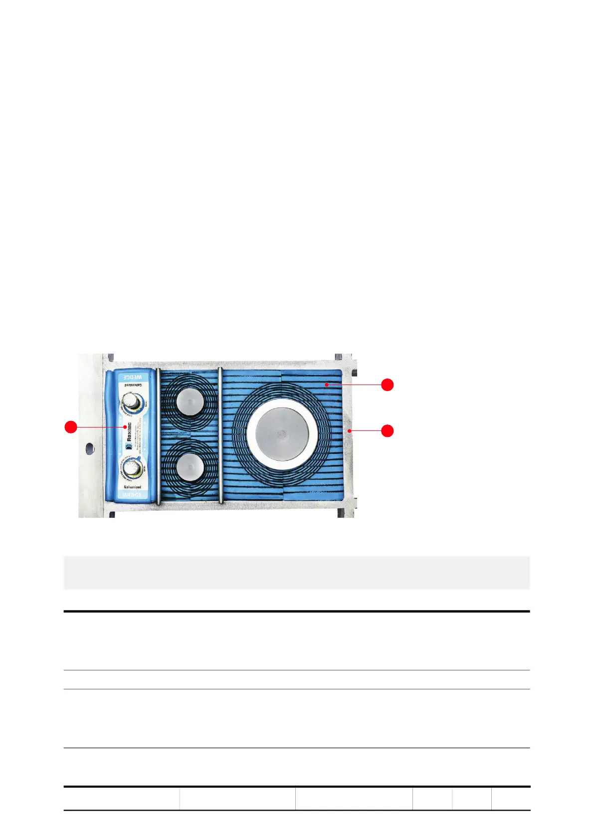
6.5.1. Frames with type 1 sealing modules
Figure 6-9 Cable entry with type 1 sealing modules
1) Compression wedge
2) Sealing module (RM120)
3) Cable entry frame
Usage – Power cables
– Ground cables
– Equipotential bonding conductors
Included in delivery – Cable entry frame
Not included in
delivery
– Sealing modules
– Accessories
– Tools
1
3