OPERATION
PRODUCT
ACS6000
DOCUMENT KIND
User manual
DOCUMENT ID.
3BHS212794 E01
REV.
N
LANG.
en
PAGE
170/266
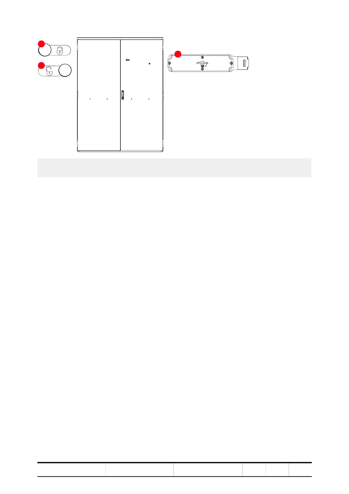
Figure 8-7 Safety switches
The safety switches are part of an interlocking circuit that prevents the doors
being opened as long as the DC link is charged. The interlocking circuit ensures
that the:
– Main power can only be connected to the drive if the doors are securely closed,
the grounding switch is in position not grounded, and the safety switches are
in position locked.
– Doors can only be opened when the main power has been disconnected, the
DC-link capacitors have been discharged, and the grounding switch is in
position grounded.
The locking bar locks and unlocks the locking mechanism of the door of a medium
voltage unit.
For more information, see “10.4.4 Unlocking and opening the doors” on page 221.
8.7. Optional switchgear and controlgear
The operating personnel must be informed about the types of switches present in
the drive and the parameter settings for opening and closing.
8.7.1. DC-link disconnector
Drives can be equipped with a manual controlled DC-link disconnector. The
location of the control switch for opening and closing depends on the
configuration of the drive. The control switch can be actuated when released by the
drive.
1) Locking bar in locked position
2) Locking bar in unlocked position
3) Safety switch