POWER ELECTRONICS AND CABINET FEATURES
PRODUCT
ACS6000
DOCUMENT KIND
User manual
DOCUMENT ID.
3BHS212794 E01
REV.
N
LANG.
en
PAGE
65/266
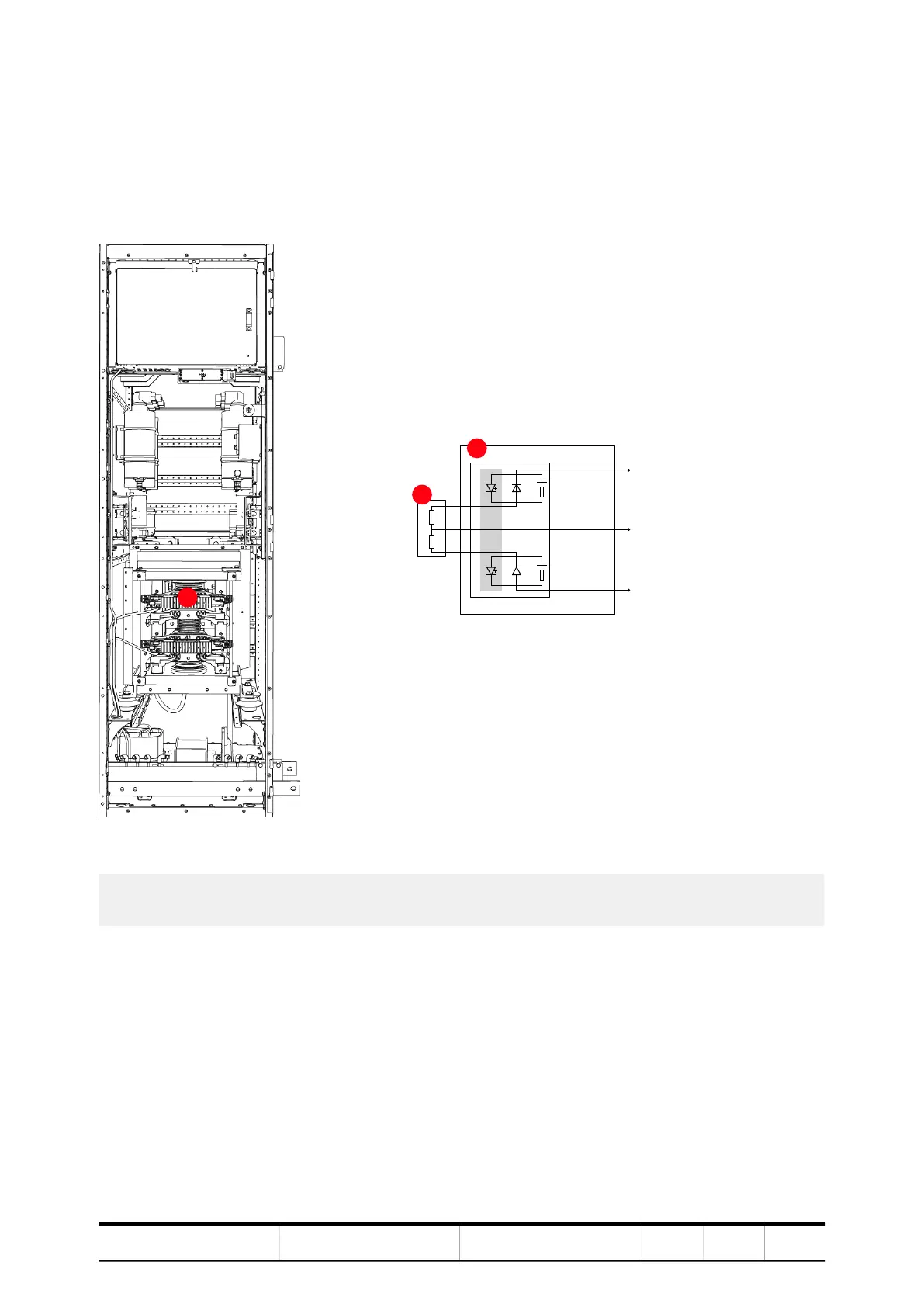
3.3.4.1. Braking chopper unit
A BCU is used when the braking scenario requires consistent energy dissipation.
The energy generated during braking is dissipated in external water-cooled
resistors, which are not part of the drive.
Figure 3-23 BCU cabinet (A) and circuit diagram (B)
1) IGCT
2) Resistor (external)
3) BCU
2
3
1