Home
Agilent Technologies
Test Equipment
93000 SOC Series
Page 100
Agilent Technologies 93000 SOC Series - Page 100
632 pages
Manual
To Next Page
To Next Page
To Previous Page
To Previous Page
Loading...
Lesson
1
–
Analog Mo
dules
100
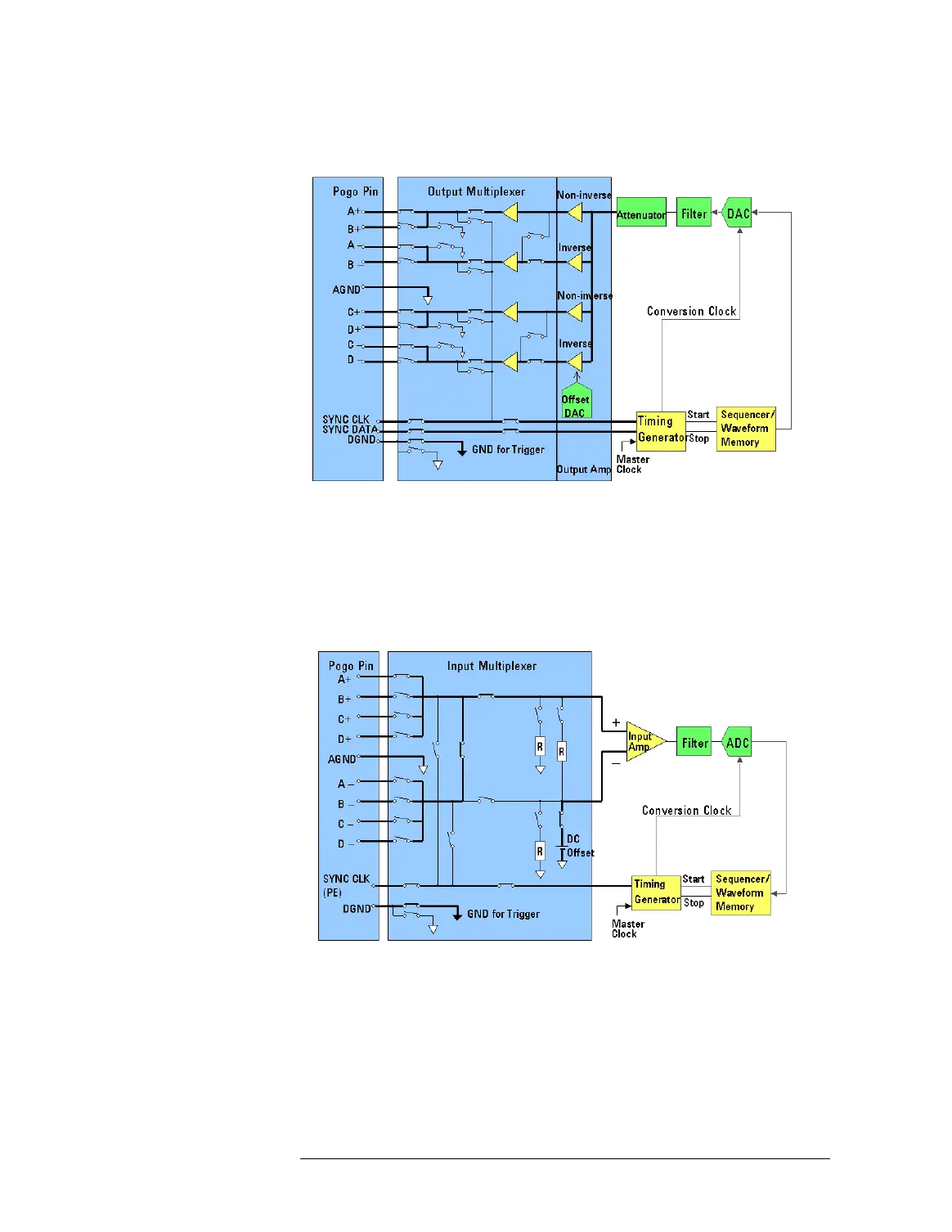
Output R
outes
(Dif
ferential i
n W
GA
/W
GB
/W
GD
)
Input
Ro
ute
s
(For di
gitizers, samplers, and
TIA
)
This connection ty
pe is used to
measure an analog wa
vef
orm.
Input Routes (Si
ng
le-Ended in
WDB/WD
A
)
99
101
Table of Contents
Main Page
Default Chapter
3
Table of Contents
3
Unit
11
Lesson
13
Training Overview
13
About this Training
15
The Study Material
19
Lesson 2
21
Introduction to the Test System
21
Introduction to the Test System
22
Components of SOC Devices
23
SOC Series Mixed-Signal System Overview
25
Questions
33
Summary and Discussion
34
Lesson
35
Introduction to the Software
35
Smartest Software Concept Overview
37
Tools for Mixed-Signal Testing
39
Analog Modules
40
Analog Modules
41
Analog Modules
45
Questions
54
Analog Modules
55
Summary and Discussion
56
Unit 2
57
Analog Hardware
57
Lesson 1
59
Analog Modules
59
Analog Modules
60
Summary of Analog Modules
61
Arbitrary Waveform Generators (AWG)
62
Waveform Digitizer
73
Sampler
87
Time Interval Analyzer
94
Pin Connections with an Analog Module's Multiplexer
99
Multi-Site Baseband Analog Source&Measure / Analog Measure (MCA)
104
Lesson
104
Addressing the Analog Modules
129
Addressing the Analog Modules
130
Locations of Analog Boards in the Testhead
131
Analog Pins of the Board
134
Identification of Analog Channels in the Software
139
Lesson 3
143
Synchronization of Analog Modules
143
Synchronization of Analog Modules
144
Synchronization + Triggering
146
Adjusting the Synchronization Timing
151
Unit 3
153
DAC Test Setup and Execution
153
Lesson 1
155
The Training DAC
155
The Training DAC
156
DAC Basics
157
Characteristics of the Training DAC
159
Mixed-Signal Test Setup Procedure
161
Summary and Discussion
164
Lesson 2
165
Waveform Digitizer Setup with the Analog Setup Tool
165
Waveform Digitizer Setup with the Analog Setup Tool
166
Functions of the Analog Setup Tool
167
Starting the Analog Setup Tool
175
Core Selection and Global Functions
177
Setting up the Analog Hardware
181
Setting up Sequencer Program and Waveform Memory Labels
184
Reviewing and Changing the Waveform Memory
192
Viewing the Relay Multiplexer Switches
194
Summary and Discussion
196
Contents
197
Lesson 3
197
Setting up the Digitizers in the Digital Clock Domain
197
Setting up the Digitizers in the Digital Clock Domain
198
What Is a Clock Domain
199
Clock Sources and Clock Distribution Overview
200
Digital Clock Domain Setup for the Digitizer
203
Summary and Discussion
208
Lesson 4
209
Defining the Signal Routing
209
Defining the Signal Routing
210
Analog Routing Basics
211
Overview of the Routing Setup Tool
213
Setting up the DAC Routing
216
Activating a Routing Set
221
Viewing the Active Routing
222
Summary and Discussion
223
Lesson 5
225
Waveform Generation with the Mixed-Signal Tool
225
Functions of the Mixed-Signal Tool
227
Starting the Mixed-Signal Tool
229
Customizing the Mixed-Signal Tool
231
Saving and Restoring Waveforms
234
Generating Waveforms
236
Downloading a Generated Waveform
248
Related Topics
250
Summary and Discussion
251
Contents
253
Lesson 6
253
Executing the DAC Linearity Test
253
Executing the DAC Linearity Test
254
DAC Linearity Measurements
255
DAC Linearity Test Parameters
261
Uploading Result Waveforms with the Mixed-Signal Tool
263
Displaying Logged Waveforms with the Mixed-Signal Tool
266
Related Topics
270
Summary and Discussion
271
Lesson 7
273
Executing the DAC Distortion Test
273
Executing the DAC Distortion Test
274
DAC Distortion Measurements
275
DAC Distortion Test Parameters
280
Analyzing Spectral Data with the Mixed-Signal Tool
282
Summary and Discussion
287
Unit 4
289
ADC Test Setup and Execution
289
The Training ADC
290
Lesson 1
291
The Training ADC
291
ADC Basics
293
Test Setup Overview for ADC Tests
299
Characteristics of the Training ADC
301
Summary and Discussion
302
Lesson 2
303
Setting up the Waveform Generator
303
Setting up the Waveform Generator
304
Waveform Generator Setup with Analog Setup Tool
305
Defining and Downloading a Waveform to the AWG
317
Signal Routing
320
Summary and Discussion
321
Contents
323
Lesson 3
323
Setting up the Digital Capturing
323
Setting up the Digital Capturing
324
Introduction to Digital Capture
325
Setup for Digital Capture
328
Summary and Discussion
340
Lesson 4
341
Executing the ADC Linearity Test
341
Executing the ADC Linearity Test
342
ADC Linearity Measurements
343
ADC Linearity Test Parameters
347
Uploading Result Waveforms with the Mixed-Signal Tool
349
Summary and Discussion
351
Lesson 5
353
Executing the ADC Distortion Test
353
Executing the ADC Distortion Test
354
ADC Distortion Measurements
355
ADC Distortion Test Parameters
357
Summary and Discussion
360
Unit 5
361
Using the Analog Clock Domain
361
Lesson 1
363
Analog Clock Domain Description
363
Clock Domains Summary
365
Clock Sources and Clock Distribution
366
Clock Distribution between Card Cages
370
Summary and Discussion
375
Lesson 2
377
Analog Clock Domain Setup
377
Overview of Analog Clock Domain Setup Parameters
379
Analog Clock Domain Setup Procedure
382
Analog Module Setup Interdependencies
387
Summary and Discussion
393
Contents
395
Using Test Methods
395
Test Method Structure
397
Test Method Overview
399
Data Types
403
Input/Output Data of Test Method Program
405
Programming Style of Test Method API
409
Test Method Apis
414
Test Method Program for DC Tests
425
Lesson 2
431
Creating a Test Method
431
Creating a Test Method
432
Overview
433
Preparations to Develop a Test Method Program
436
Using the Text Editor for Editing a Test Method Program
441
Compiling and Linking Test Method Programs
445
Registering a Test Method Shared Library
447
Setting up Testmethod-Based Test Suite
448
Executing Testmethod-Based Test Suite
453
Debugging Test Method Programs
456
Debugging Tests Using Hardware Response Emulator
463
Unit 7
467
Time Interval Analyzer
467
Lesson 1
469
TIA Overview
469
TIA Overview
470
Front-End Module and Time Interval Analyzer (TIA)
471
Setup and Test Execution Overview
473
TIA Setup
474
Summary and Discussion
475
TIA Setup
477
Lesson 2
478
TIA Setup
478
Overview
479
Pin Configuration for the TIA
480
Front-End and TIA Setup
481
Defining the Routing
493
Summary and Discussion
495
Lesson 3
497
TIA Test Method Programming and Test Execution
497
TIA Test Method Programming and Test Execution
498
Test Method Flow
499
TIA API Functions
501
TIA Example Test Method
504
Summary and Discussion
507
Multi-Site Test
511
Lesson 1
512
Multi-Site Test
512
Overview
513
Defining Pin Configuration
515
Setting up Flags for Multi-Site Testing
516
Test Method Program for Multi-Site Testing
517
Lesson 2
527
DUT Board Design Considerations
527
DUT Board Design Considerations
528
DUT Board Overview
529
DUT Board Design Consideration
531
Grounding and Signal Shielding
533
Printed Circuit Board
536
Troubleshooting Noise Problems
539
Summary and Discussion
540
Special Synchronization Options
541
Special Synchronization Options
542
Master/Slave Trigger Function
543
Related product manuals
Agilent Technologies 3070
116 pages
Agilent Technologies 8156A
291 pages
Agilent Technologies 54621A
276 pages
Agilent Technologies N9310A
188 pages
Agilent Technologies U1602B
227 pages
Agilent Technologies E6198B
318 pages
Agilent Technologies E7495A RF
15 pages
Agilent Technologies 8960 Series
165 pages
Agilent Technologies 5000 Series
126 pages
auroraSonata
336 pages
E4406A VSA Series
420 pages
InfiniiVision 5000 Series
428 pages