Lesson 2 – Addressing the Analog Modules
135
Arbitrary Waveform Generator (AWG)
The High Resolution AWG (WGA), High Speed AWG (WGB) and
500M AWG (WGD) can generate a waveform at one of 8 single-
ended or 4 differential channels.
The 30M AWG (WGE) has two AWG cores. A WGE AWG core can
generate a waveform at one of 4 single-ended or 2 differential
channels.
The Ultra High Speed AWG (WGC) can generate a waveform at one
of 4 single-ended or 2 differential channels.
The 4.1G AWG (WGF) can generate a waveform at 4 differential
channels.
To control the execution of each AWG, the trigger line SYNC CLK
or TRIGGER is used.
SYNC DATA: Currently not used.
DGND: Digital ground on the AWG.
AGND: Analog ground on the AWG.
FGND: Floating ground. Not connected to any ground. For future expansion.
For the AWGs except WGC and WGF, the A-, B-, C-, and D- pins
can be used to generate a single-ended signal (non-inverted signal).
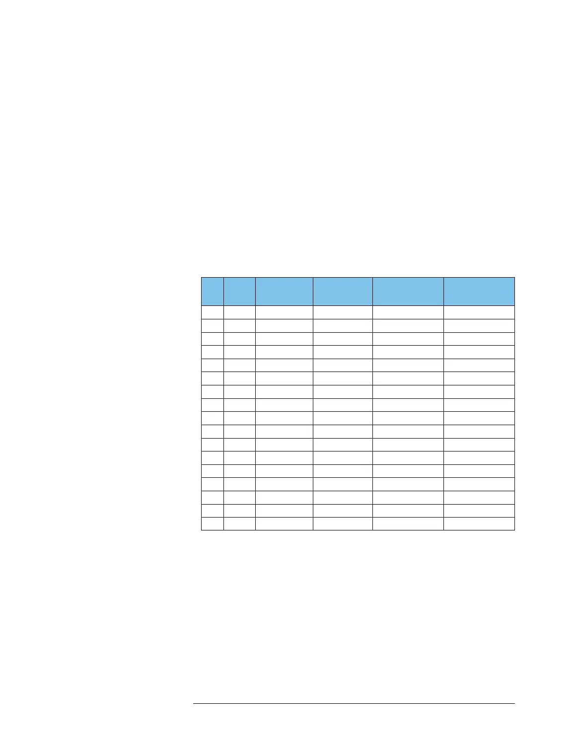
Pad
GND
Pad
a
WGA/WGB/
WGD
WGF
a
WGE
b
WGC
c
01 DGND STATUS2 out STATUS2 out STATUS2 out Marker (core 2)
02 DGND Marker (core 1)
03 DGND SYNC DATA SYNC DATA Trigger (core 2)
04 DGND SYNC CLK SYNC CLK SYNC CLK Trigger (core 1)
05 FGND
06 FGND
07 AGND
08 AGND
09 AGND D- (+) D- D- (+) (core 2) D- (core 2)
10 AGND D+ D+ D+ (core 2) D+ (core 2)
11 AGND C- (+) C- C- (+) (core 2) C- (core 2)
12 AGND C+ C+ C+ (core 2) C+ (core 2)
13 AGND B- (+) B- B- (+) (core 1) B- (core 1)
14 AGND B+ B+ B+ (core 1) B+ (core 1)
15 AGND A- (+) A- A- (+) (core 1) A- (core 1)
16 AGND A+ A+ A+ (core 1) A+ (core 1)
17 AGND
a
The ground of the signal generated by the WGF is in common with the digital ground,
in contrast to the other analog modules.
b
A WGE module contains two AWG cores that share the SYNC CLK, SYNC DATA, and
STATUS2 pins.
c
For WGC, installing AWG core 2 (AWG instrument 2) is optional. The function of the
WGC pins differs from that of the other AWGs. Instead of STATUS2 or reserved
(STATUS1), a “Marker” states whether a waveform generating process is on or off.

 Loading...


