Lesson 3 – Setting up the Digitizers in the Digital Clock Domain
201
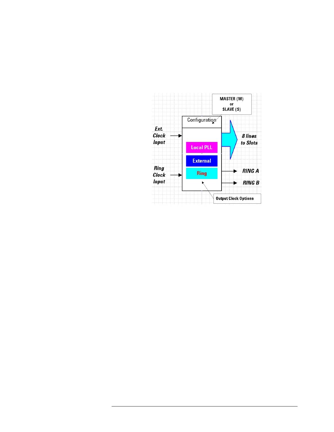
distribute the clock signal to the boards installed in the eight slots
of the card cage.
Clock Board Input and Output Lines
There are three modes of operation for a clock board in a card
cage which determine how to send the output clock signal to the
eight boards installed in the slots of the card cage, and to the next
card cage’s clock board via the Ring A and Ring B lines:
• Local PLL
This is the mode for the clock board that operates as the master.
The board generates the clock signal with the on-board PLL.
• External
This is the mode for a clock signal which is generated externally by
an AMC and is fed to the External Clock Input of the clock board.
The board forwards this signal to the output. In the digital domain,
the AMC input can only be made to the master clock board.
• Ring
This is the mode to forward the Ring Clock Input signal. This is the
normal mode of operation for all clock boards, except for the
master clock board.

 Loading...


