Lesson 1 – The Training ADC
296
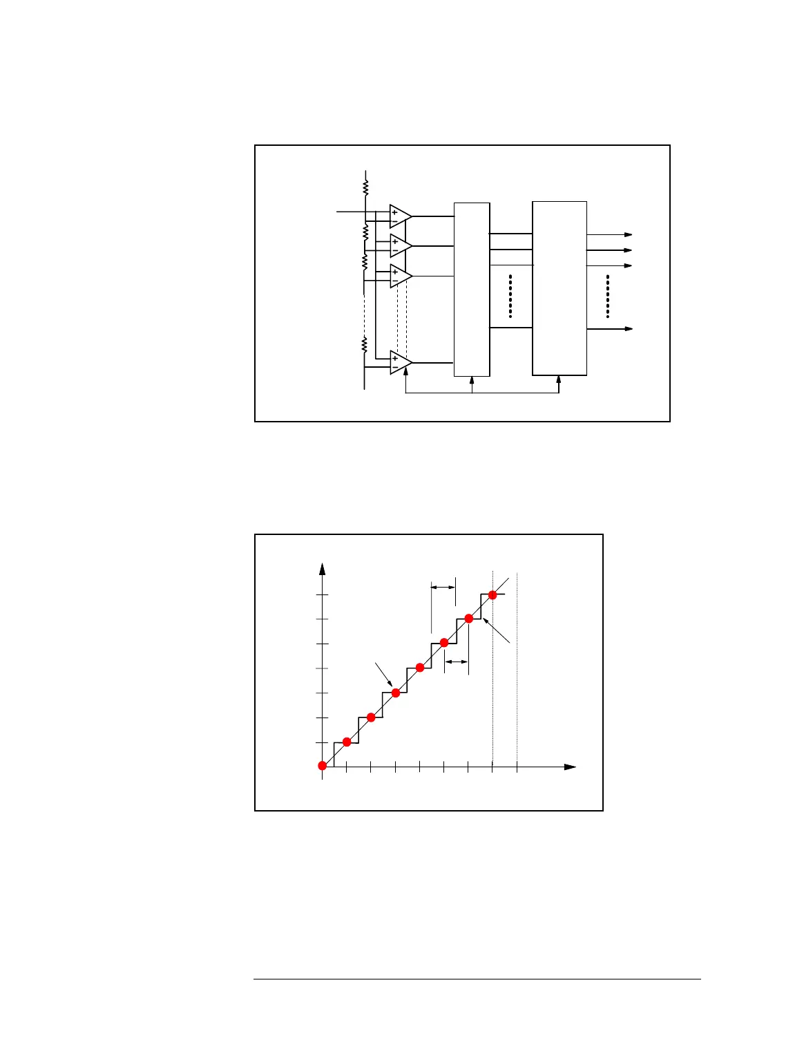
Flash ADC Block Diagram
ADC Input-Output Chart
Linear ADCs have a transfer characteristic as shown below:
Input-Output Chart of an Ideal 3-bit ADC
FS = Full analog scale In case of a 3-bit ADC, as shown above, the analog equivalent to
1 LSB is 1/8 of the full analog scale (FS).
DeviceLSB = FS / 2
n
In general, the analog equivalent to 1 LSB is FS divided by 2
n
,
where n = number of bits. The analog equivalent to 1 LSB is also
called DeviceLSB.
Decode logic
Output register
n
n lines
2 -1
n
Analog
input
comparators
Sampling clock
R
R
R
R
–Vref
+Vref
Analog Input
Binary Output Code
1/4
1/2 FS
1/8
3/8
5/8
3/4
7/8
1 LSB
code
width
code
center
code transition
001
010
011
100
101
110
111
000
 Loading...


