Lesson 1 – Analog Clock Domain Description
373
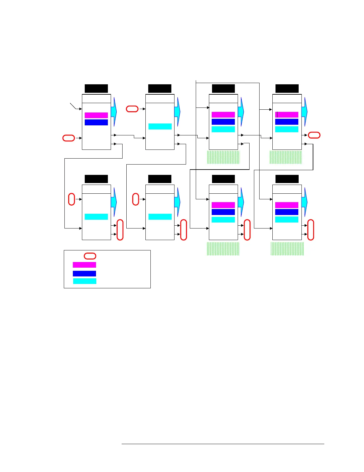
Clock Distribution 1024 Testhead (with AMC, Digital Domain and Analog
Domain
The clock distribution and generation is the same as for the 512
testhead with AMC, except for the additional Ring B connections,
which operate exactly like the Ring A connections, and the fact
that the boards in cages 8, 2, 4 and 6 can operate as described
before for the boards 4 and 2 of the 512 testhead.
The 10 MHz Reference Clock
In addition to all the clock connections shown above, the clock
boards in all card cages of the test system are frequency locked by
a 10MHz reference clock signal which is distributed to all of them.
This reference signal is generated by a test system inherent
oscillator, if no AMC is installed. If an AMC is installed, the
reference signal is always generated by the AMC. The AMC
Master
RING A
RING B
Ring
Ext.
C. Cage 5
NC
SLOTS
Slave
RING A
RING B
Ring
Ext.
C. Cage 3
NC
SLOTS
Slave
RING A
RING B
Ring
Ext.
C. Cage 8
SLOTS
Slave
RING A
RING B
Ring
Ext.
C. Cage 2
SLOTS
NC
Local PLL
Ring
External
Ring
Local PLL
External External
Ring
Slave
RING A
RING B
Ring
Ext.
C. Cage 1
NC
SLOTS
Slave
RING A
RING B
Ring
Ext.
C. Cage 7
NC
NC
SLOTS
Slave
RING A
RING B
Ring
Ext.
C. Cage 4
SLOTS
Slave
RING A
RING B
Ring
Ext.
C. Cage 6
SLOTS
Local PLL
Ring
Ring
Local PLL
External External
Ring
NC
NC
NC
Ring
Local PLL
NC
Not Connected
Local PLL
External
Ring
Clock generated by PLL
Clock from AMC
Clock forwarded from the
previous clock board
Analog Card Cage Analog Card Cage
Analog Card Cage Analog Card Cage
AMC
(digital domain)
AMC
(analog domain)

 Loading...


