Lesson 2 – TIA Setup
482
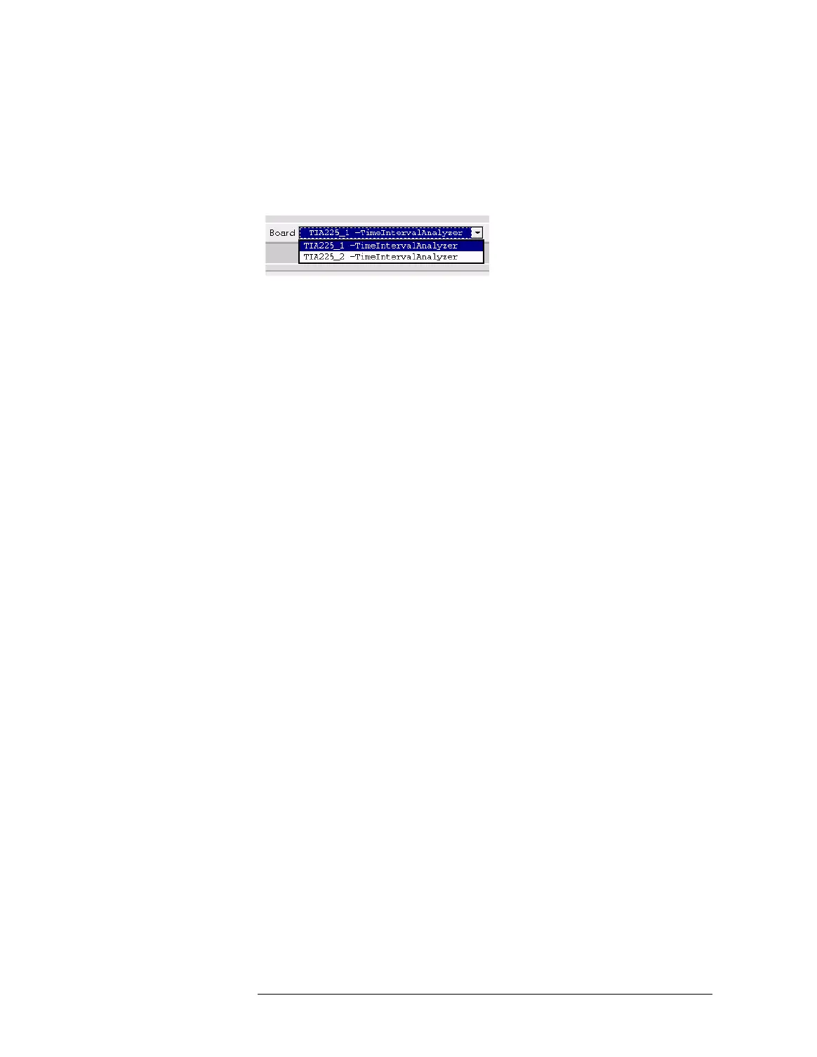
To do this, you select the instrument TIAxxx_1 or TIAxxx_2
directly from the drop down list of the B
OARD field (xxx is the slot
number where the front-end module is installed, typically 225).
Selecting the TIA Instrument (Core)
NOTE
You can also select any of the defined TIA pins from the drop down
list of the P
IN field, but you will be prompted to specify the TIA core
as well in the B
OARD field, as a TIA pin can be connected to either of
the two TIA cores, and thus selecting one does not yet define for
which of the cores you want to make the settings.
The type of the selected TIA instrument will be displayed on the
Hardware Settings page (like DTS 2077, the High Performance TIA,
in the figure above). The Hardware Settings page and the setup
procedure for the different TIA cores (High Performance TIA (DTS
2077) or General Purpose TIA (DTS 1000) are identical. The two
TIA cores only differ in their measurement performance.
Front-End Module Settings
The front-end module performs the termination for the input pins,
the signal conditioning of the incoming signals and the routing of
input signals.
In the Hardware Settings page you make the settings for the
• Input Termination
- termination impedance Z
in
- termination voltage
• Signal Conditioning
- threshold voltage for the rising edge (threshold for ‘high’ level)
- threshold voltage for the falling edge (threshold for ‘low’ level)
The routing settings are made with the Routing Setup Tool. This is
described later in this lesson.

 Loading...


