Lesson 1 – Analog Modules
66
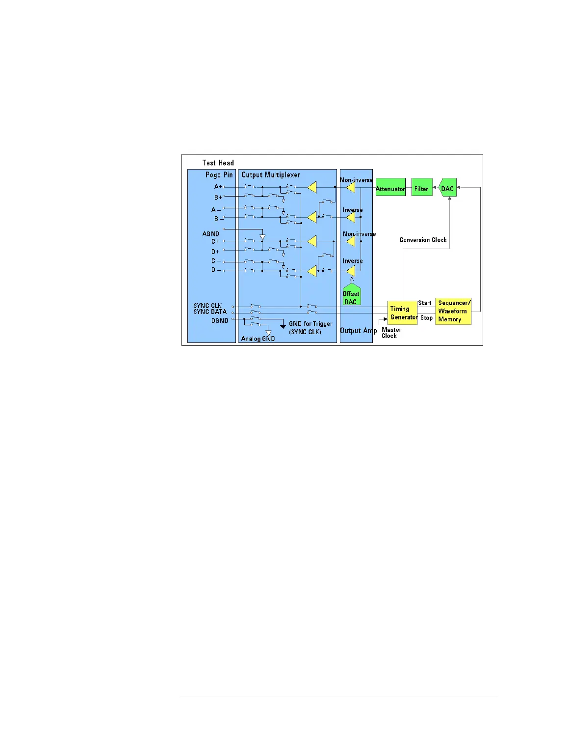
High Resolution / High Speed / 500M AWG
The following figure shows the block diagram of the High
Resolution AWG (WGA), High Speed AWG (WGB) and 500M AWG
(WGD):
Block Diagram of WGA, WGB and WGD
All the components of these AWGs are placed on a single board
which is installed in the testhead.
1 Output Multiplexer
For A+, A-, B+, B-, C+, C-, D+, and D- AWG pins, the output
multiplexer is used to specify single-ended or differential outputs.
The allowable pin combinations for the differential outputs are
A+/A-, B+/B-, C+/C-, and D+/D-.
Each AWG has four buffered outputs so that fan out to multi-site is
made simple. Hence, a single-ended signal can be output from
maximum four pogo pins at the same time as follows:
All or some of combinations: A+ or B+, A- or B-,
C+ or D+, C- or D-
A pair of differential signals can be output from maximum two
pogo pin pairs at the same time as follows:
All or some of combinations: Pair of A+/A- or B+/B-,
Pair of C+/C- or D+/D-
In addition, the multiplexer can make the following routes for
these pins and the SYNC_CLK pin:
• DC routes to perform DC measurement at one of the AWG pins via
the SYNC CLK pin.

 Loading...


