Lesson 1 – Analog Modules
83
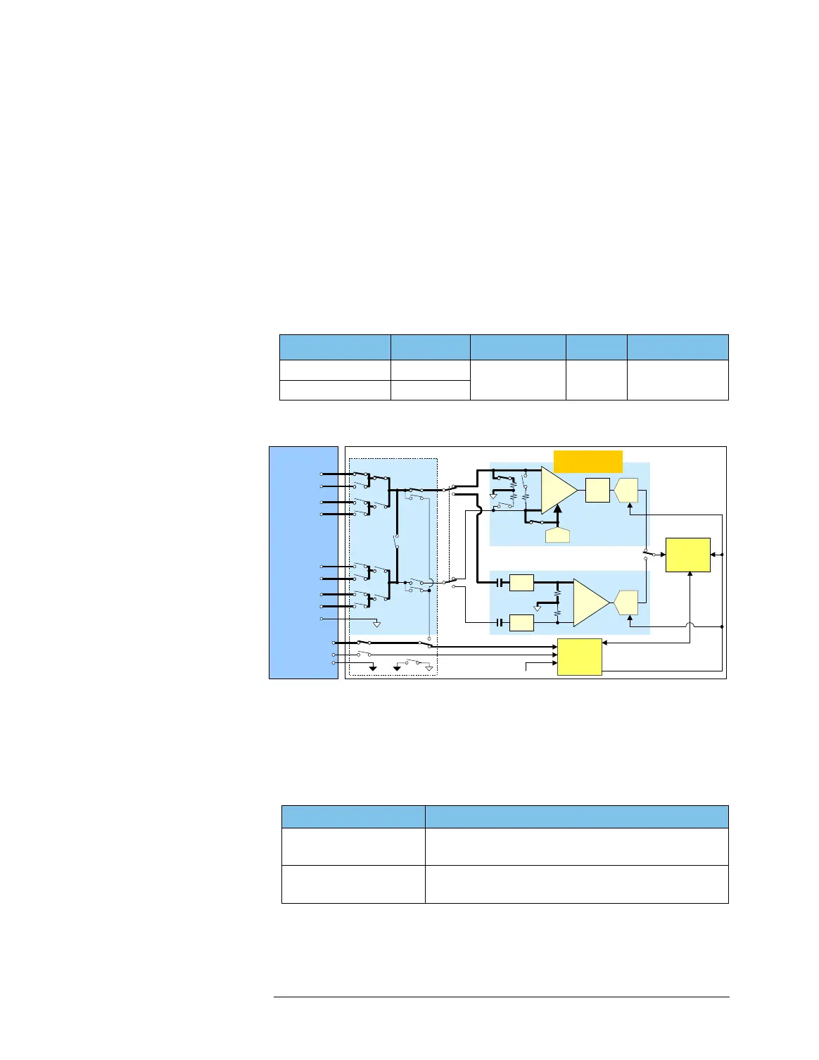
100MHz Digitizer
The 100MHz Digitizer (software identifier: WDG) is a 105 Msps 14-
bit digitizer. This module has two signal paths with different A/D
converters. The respective signal paths are called the DC coupling
mode and AC coupling mode. The DC coupling mode is for
standard analog measurements and the AC coupling mode is for
high dynamic range analog measurements such as set-top-box
application. You can switch these modes according your test needs
when you set up a test. These modes share the pogo pins, input
multiplexer, sequencer, waveform memory as shown in the
following figure.
Block Diagram of WDG (Single-ended input routes shown with bold lines)
The WDG is a single-slot analog module installed in the testhead, and
has one digitizer core.
The single-ended signal or differential signal can be captured from
the pins shown in the following table.
Mode Bandwidth Sampling Rate Resolution Waveform Memory
DC coupling mode DC - 100 MHz
30 M - 105 Msps 14 bits 16 M samples
AC coupling mode 250k - 100MHz
Input Possible Input Pin in Input Route of WDG
Single-ended input 1 input only of 8 inputs:
A+, B+, C+, D+, A-, B-, C-, or D-
Differential input 1 input only of 4 inputs:
A+&A- pair, B+&B- pair, C+&C- pair, or D+&D- pair
Pogo Pin
Input Multiplexer
A+ (16/Mode1)
B– (13/Mode6)
A– (15/Mode5)
B+ (14/Mode2)
DGND
Master Clock
CCLK Stop/Sequencer Start
SYNC CLK (04)
SYNC DATA (03)
Timing
Generator
C– (11/Mode7)
D– (09/Mode8)
C+ (12/Mode3)
D+ (10/Mode4)
AGND
Conversion Clock (CCLK)
Filter
Sequencer/
Waveform
Memory
(GND for SYNC CLK)
DC Coupling Mode
Input
Amp
R1 R2
R1
Offset DAC
ADC
+
-
R1: 37.5, 50, or 10k
R2: 100
AC Coupling Mode
C
Input
Amp
50
50
+
-
Filter
C
Filter
ADC

 Loading...


