Lesson 1 – Analog Modules
82
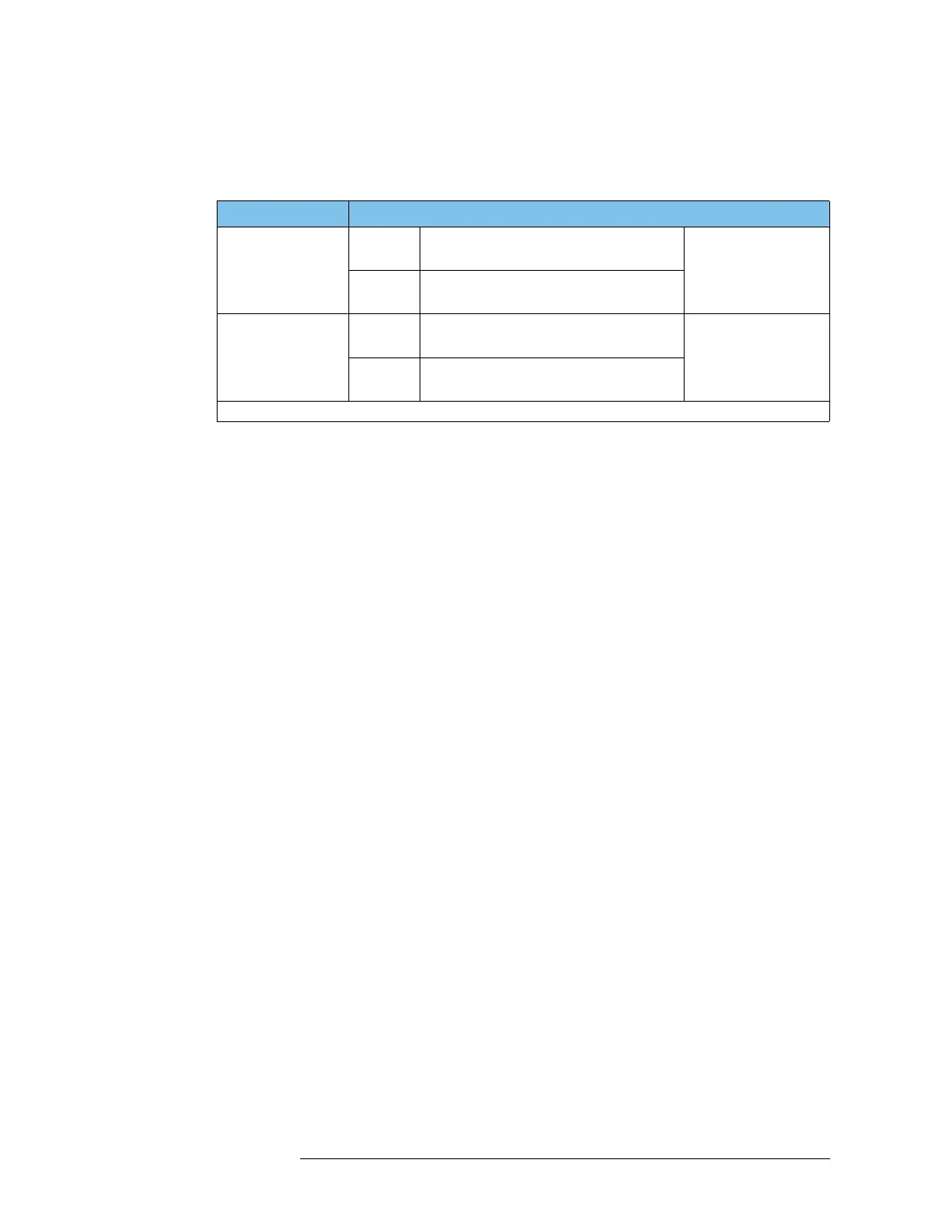
The single-ended signal and differential route can be made from
the pins shown in the following table.
Each input pin belongs to one digitizer core only, and is not
shared by the other core.
In addition to the input routes, the DC routes and loop back
routes are available in the WDE.
All routing is switched by the input multiplexer.
For other components in the digitizer (input amplifier, filter, ADC,
timing generator, sequencer, waveform memory, and SYNC_DATA
pin), see the description in “High Resolution / High Speed
Digitizer” on page 79.
Input Possible Input Pin in Input Route of WDE
Single-ended input
In core 1 1 input only of 4 inputs:
A+, B+, A-, or B-
8 inputs per module.
2 single-ended inputs
simultaneously by us-
ing core1 and core 2
In core 2 1 input only of 4 inputs:
C+, D+. C-, or D-
Differential input
In core 1 1 input only of 2 inputs:
A+&A- pair or B+&B- pair
4 inputs per module.
2 differential inputs
simultaneously by us-
ing core 1 and core 2
In core 2 1 input only of 2 inputs:
C+&C- pair or D+&D- pair
One single-ended input in a core and one differential input in the other core can also be made simultaneously.

 Loading...


