Configuring Spanning Tree Parameters MST General Overview
OmniSwitch AOS Release 8 Network Configuration Guide December 2017 page 6-13
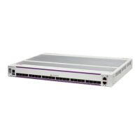
Per-VLAN Mode STP/RSTP
In the above per-VLAN mode example:
• Both switches are running in the per-VLAN mode (one Spanning Tree instance per VLAN).
• VLAN 100 and VLAN 200 are each associated with their own Spanning Tree instance.
• The connection between 3/1 and 2/1 is left in a forwarding state because it is part of the VLAN 100
Spanning Tree instance and is the only connection for that instance.
• The connections between 4/8 and 5/2 and 4/2 and 5/1 are seen as redundant because they are both
controlled by the VLAN 200 Spanning Tree instance and connect to the same switches. The VLAN
200 Spanning Tree instance determines which connection provides the best data path and transitions
the other connection to a blocking state.
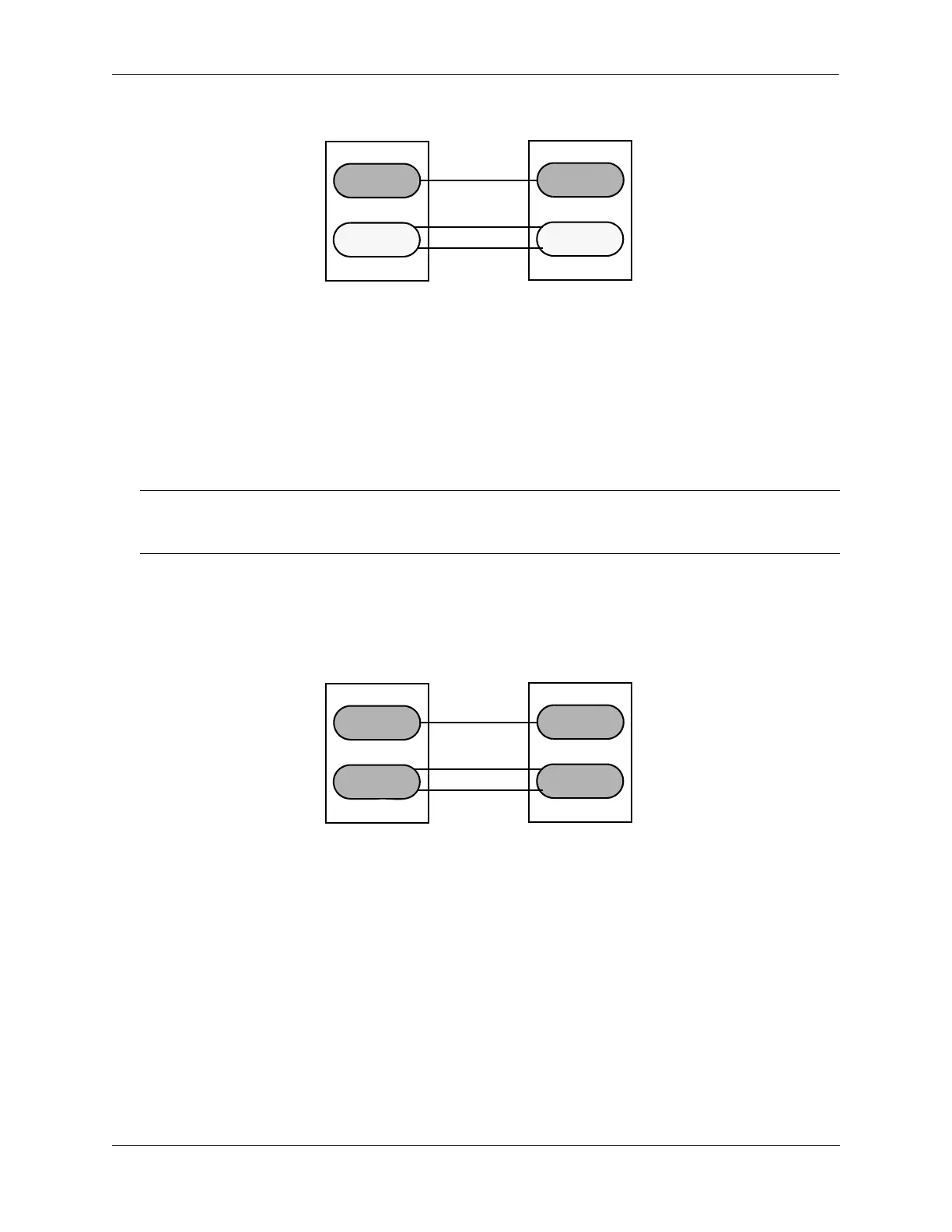
Flat Mode STP/RSTP (802.1D/802.1w)
In the above flat mode STP/RSTP example:
• Both switches are running in the flat mode. As a result, a single flat mode Spanning Tree instance
applies to the entire switch and compares port connections across VLANs to determine which
connection provides the best data path.
• The connection between 3/1 and 2/1 is left forwarding because the flat mode instance determined that
this connection provides the best data path between the two switches.
• The 4/8 to 5/2 connection and the 4/2 to 5/1 connection are considered redundant connections so they
are both blocked in favor of the 3/1 to 2/1 connection.
Note. If additional switches containing a VLAN 100 are connected to the switches in this diagram, then the
3/1 to 2/1 port connection gets into blocking state. The port connection is converted to blocking state, only
if the VLAN 100 Spanning Tree instance determines it is required, to avoid a network loop.
VLAN 200
VLAN 100
VLAN 200
2/1
3/1
4/2
4/8
5/2
5/1
||
VLAN 100
VLAN 200
VLAN 100
VLAN 200
2/1
3/1
4/2
4/8
5/2
5/1
||
VLAN 100
||
 Loading...