Configuring IP Tunneling
OmniSwitch AOS Release 8 Network Configuration Guide December 2017 page 15-37
Consider the following when configuring the IPIP tunnel interfaces:
• A switch can support up to 127 IPIP tunnel interfaces.
• IPIP tunnel interfaces are included in the maximum number of IP interfaces that are supported on the
switch.
Tunneling Operation
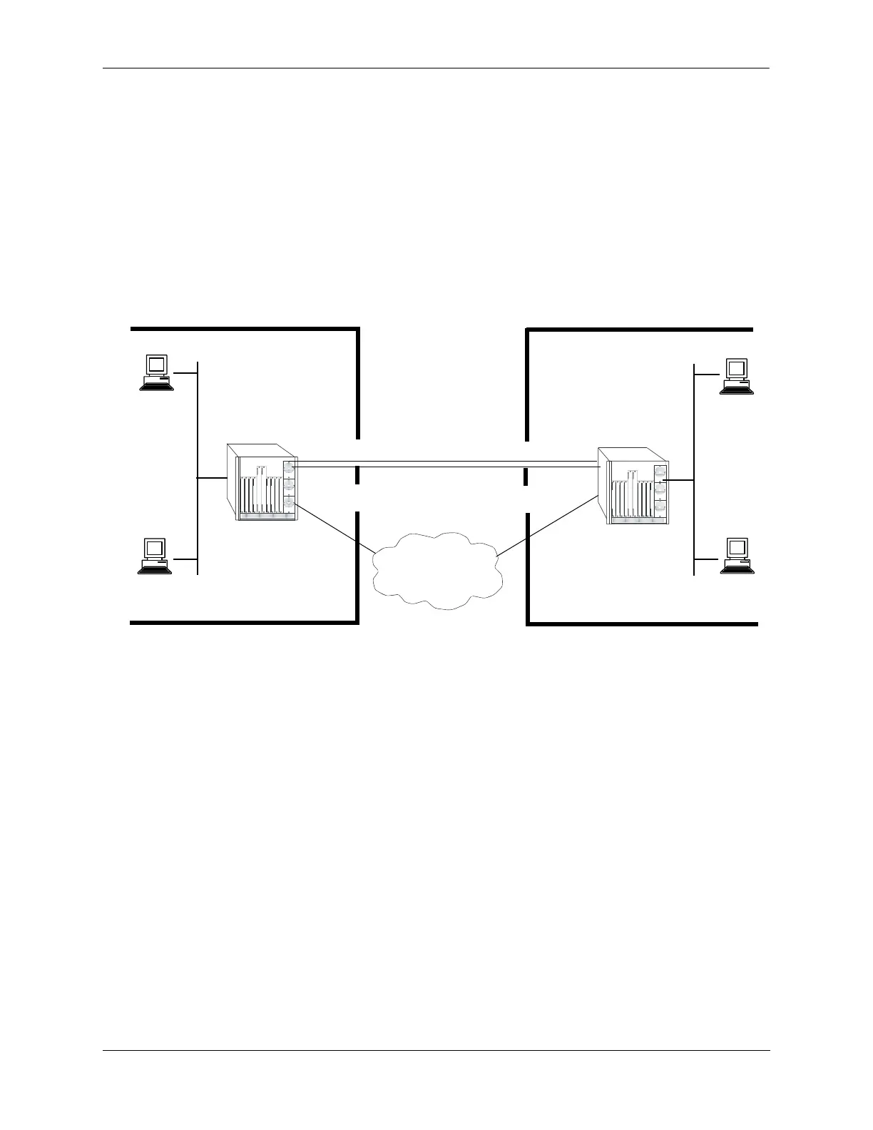
The following diagram illustrates how packets are forwarded over the tunnel.
In the given diagram, IP packets flowing from the private IP network 50.0.0.0 to the private IP network
40.0.0.0 are encapsulated by the tunneling protocol at switch A and forwarded to switch B. Intermediate
switches route the packets using addresses in the delivery protocol header. Switch B extracts the original
payload and routes it to the appropriate destination in the 40.0.0.0 network.
The tunnel interface is identified as being up when all of the following are satisfied:
• Both source and destination addresses are assigned.
• The source address of the tunnel is one of the switch's IP interface addresses that is either a VLAN or
Loopback0 interface.
• A route is available to reach the destination IP address. A route whose egress interface is a VLAN-
based interface is available for its destination IP address. The switch supports assigning an IP address
as well as routes to a tunnel interface.
This section describes how to configure a tunnel interface using GRE and IPIP, using Command Line
Interface (CLI) commands.
Private IP Network
50.0.0.0
Private IP Network
40.0.0.0
Switch A
Switch B
IP Host
50.0.0.1
IP Host
IP Host
40.0.0.1
IP Host
24.24.24.2
24.24.24.1
Tunnel Endpoint
23.23.23.1
Tunnel Endpoint
155.2.2.2
Outer IP Header : 23.23.23.1, 155.2.2.2
Inner IP Header : 50.0.0.1, 40.0.0.1
 Loading...