Configuring Spanning Tree Parameters Sample Spanning Tree Configuration
OmniSwitch AOS Release 8 Network Configuration Guide December 2017 page 6-43
Sample Spanning Tree Configuration
This section provides an example network configuration in which the Spanning Tree Algorithm and
Protocol has calculated a loop-free topology. In addition, a tutorial is also included that provides steps on
how to configure the example network topology using the Command Line Interface (CLI).
Note that the following example network configuration illustrates using switches operating in the per-
VLAN Spanning Tree mode and using RSTP (802.1w) to calculate a single data path between VLANs.
See “MST General Overview” on page 6-12 for an overview and examples of using MSTP (802.1s).
Example Network Overview
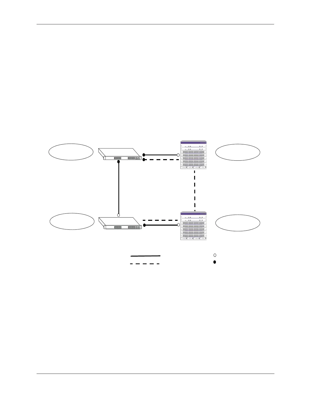
The following diagram shows a four-switch network configuration with an active Spanning Tree topology,
which was calculated based on both configured and default Spanning Tree parameter values:
Example Active Spanning Tree Topology
In the above example topology:
• Each switch is operating in the per-VLAN Spanning Tree mode by default.
• Each switch configuration has a VLAN 255 defined. The Spanning Tree administrative status for this
VLAN was enabled by default when the VLAN was created.
• VLAN 255 on each switch is configured to use the 802.1w (rapid reconfiguration) Spanning Tree
Algorithm and Protocol.
• Ports 2/1-3, 2/8-10, 3/1-3, and 3/8-10 provide connections to other switches and are all assigned to
VLAN 255 on their respective switches. The Spanning Tree administrative status for each port is
enabled by default.
VLAN 255 Bridge ID
VLAN 255 Bridge ID
VLAN 255 Bridge ID
VLAN 255 Bridge ID
Forwarding
Blocking
Root Port
Designated Port
10, 00:d0:95:00:00:01
32768, 00:d0:95:00:00:04
32768, 00:d0:95:00:00:03
32768, 00:d0:95:00:00:02
Path Cost
PC
PC=4 3/3
(Root Bridge)
(Designated Bridge)
2/1
2/10
2/2
2/3
3/10
3/12/9
3/8
PC=4
3/2
3/9
PC=4
PC=19
PC=4
PC=19
Switch C
Switch A
Switch D
Switch B
2/8
 Loading...