3-50 PN: 10580-00321 Rev. M S331L UG
3-9 C&A Menus Cable and Antenna Measurements
3-9 C&A Menus
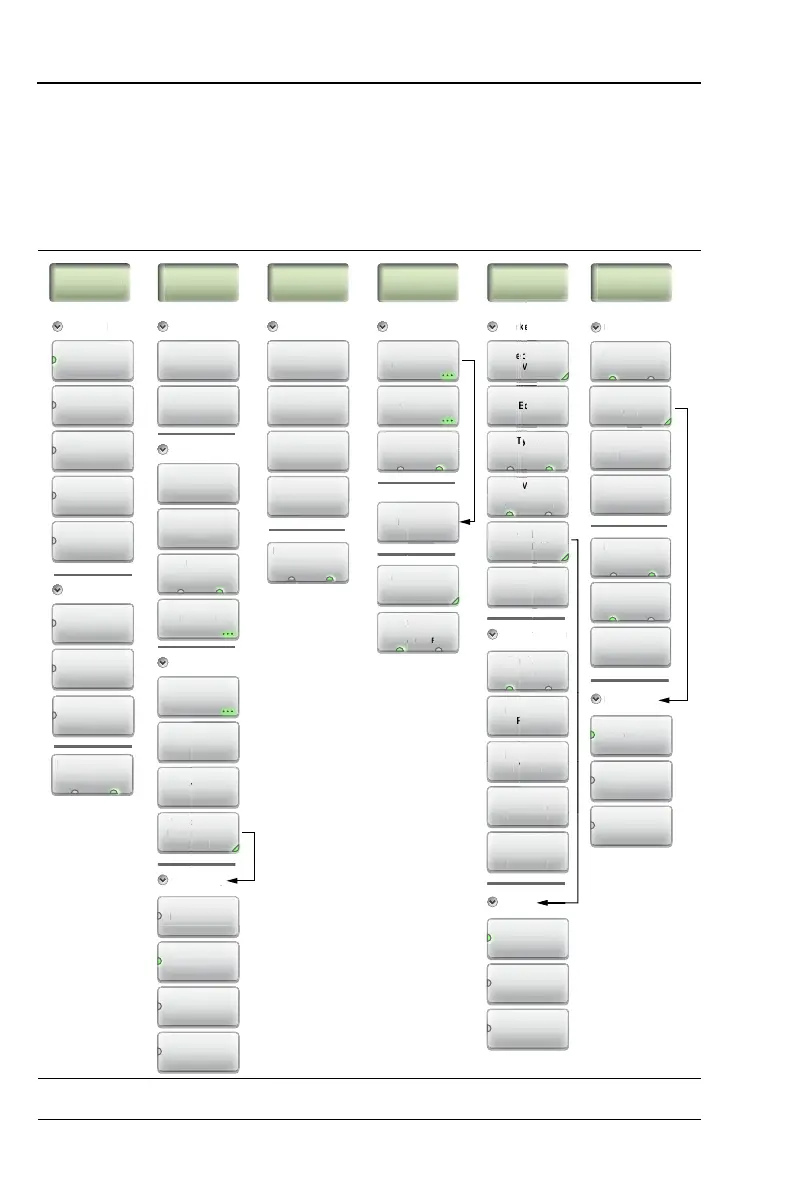
Figure 3-38 and Figure 3-39 show the map of the Cable and Antenna
Analyzer menus. The following sections describe main menus and
associated submenus. The submenus are listed in the order they appear
on the display from top to bottom under each main menu.
Figure 3-38. Menu Keys (1 of 2)
Stop Distance
(D2)
Start Distance
(D1)
Freq/Dist Amplitude Marker Limit
Peak
between
M1 & M2
Valley
between
M1 & M2
M1
On O
Type
Ref Delta
Frequency
Stop
Frequency
(F2)
Marker to
Peak
Display
Mkr + Table
Marker to
Valley
Start
Frequency
(F1)
DTF Aid
Distance
Top
Bottom
Autoscale
Edit
Fullscale
Amplitude
Units
Sto
D
stance
TF Ai
nits
mft
Cable List
Select (1-8)
M1
Marker Setup
Cable Loss
DTF Setup
Prop Velocity
Marker Search
Windowing
p
i
(
1
r
a
Windowing
Nominal Side
Lobe
e
ocity
Windowin
owin
na
Si
o
e
Marker Preset
Measurement
Standard
Return Loss
Stan
ar
Ret
rn L
ss
DTF
Return Loss
Cable Loss
VSWR
DTF VSWR
Rectangular
ectan
ula
Nominal
Side Lobe
Low
Side Lobe
Minimum
Side Lobe
Display
Mkr + Table
Displa
r + Ta
e
Mkr Only
O
Calibration
Cal Correction
n
Ma
Re
a
Correctio
tar
a
i
rat
al In
Measure
Calibration
Cal Type
Standard Flex
Limit Alarm
On O
Move Active
Limit
Limit Preset
Pass/Fail Msg
e
rese
imit A
arm
imi
Pr
ass/Fai
Ms
-8
etu
Limi
Upper Lower
Edit Segments
Tracking
Ma
Ma
On O
Advanced
Smith Chart
1-Port Phase
Display Format
Cab
rop
in
Displa
Format
Single Dual
Ref. Impedance
e
. Im
edance
50 Ω 75 Ω
Smith Chart only
Transmission
(Ext. Sensor)
Cal Method
OSL
isp
M
r +
rker
l T
p
tand
al Metho
Limi
M
ve Active
iv
Limi
pper
wer
Edit Se
ment
L
m
t St
t
ea
ween
a
r
er to
ea
r
er to
L
m
t Stat