3-52 PN: 10580-00321 Rev. M S331L UG
3-10 Measurement Menu Cable and Antenna Measurements
3-10 Measurement Menu
Key Sequence: Measurement
Standard:
Return Loss: Return Loss is used to characterize RF
components and systems. The Return Loss indicates
how well the system is matched by taking the ratio of
the reflected signal to the incident signal, and
measuring the reflected power in dB.
DTF Return Loss: The DTF measurement displays
return loss values versus distance. If the frequency
measurements fail or indicate a problem in the system,
then the DTF measurement can be used to identify and
pinpoint the exact location of the problem. The DTF
measurement shows the return loss value of all the
individual components including connector pairs and
cable components.
Cable Loss: The cable loss test verifies the signal
attenuation level of the cable.
VSWR: Press the VSWR submenu key to view the
impedance match in VSWR. VSWR is a ratio of voltage
peaks to voltage valleys.
DTF VSWR: Press this submenu key to display VSWR
values versus distance. If the frequency measurements
fail or indicate a problem in the system, then the DTF
measurement can be used to identify and pinpoint the
exact location of the problem. The DTF measurement
shows the VSWR value of all the individual
components including connector pairs and cable
components.
Advanced and Common: Shown on next page.
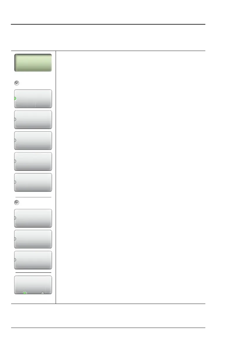
Figure 3-40. Measurement Menu (1 of 2)
Measurement
Standard
Return Loss
n
t
rn
DTF
Return Loss
Cable Loss
VSWR
DTF VSWR
Advanced
Smith Chart
1-Port Phase
Display Format
Disp
a
Form
Single Dual
Transmission
(Ext. Sensor)