Home
Ateis
Security System
IDA8 Series
Ateis IDA8 Series User Manual
4
of 1
of 1 rating
535 pages
Give review
Manual
Specs
To Next Page
To Next Page
To Previous Page
To Previous Page
Loading...
Te
chnica
l
D
a
ta
49
5
© 20
20, A
T
E
ÏS. A
l
l
r
i
ghts
res
er
v
ed.
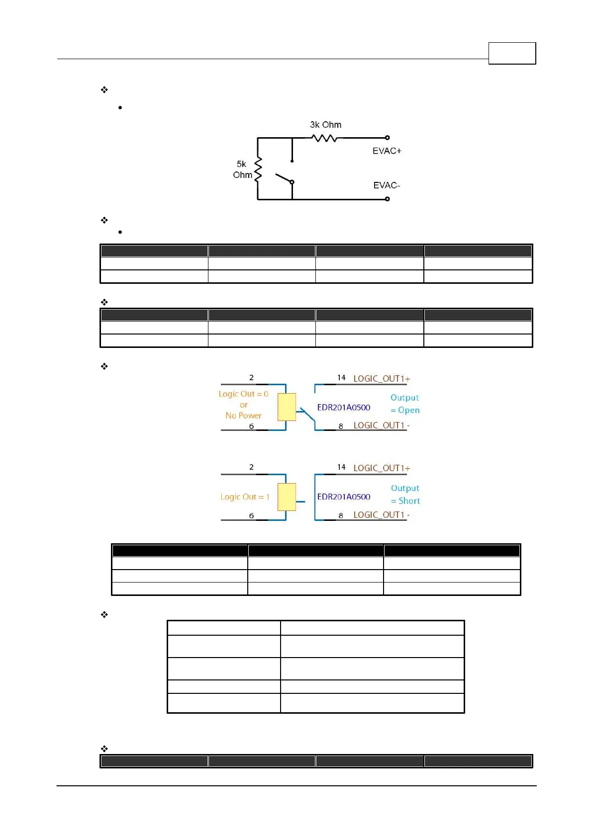
Ev
ac
uation I
np
ut
s
(C
o
nt
act
M
od
e)
4 s
t
at
us:
On,
Of
f
,
Op
en and
S
ho
rt
Ev
ac
uation I
np
ut
s
(Voltage
Mode
)
On
V
olt
ag
e:
I
t
em
Minim
um
Max
imum
U
nit
H
igh
18
72
VDC
Lo
w
-
0.8
VDC
C
ontac
t
Ou
t
puts
+
E
V
AC,
Fault
S
t
at
e Outpu
t
s
I
t
em
Minim
um
Max
imum
U
nit
Volt
age
-
10
0
VDC
C
ur
ren
t
-
0.5
ADC
C
ontac
t
Ou
t
put
R
elay
Co
nt
act O
u
t
pu
t
C
ontac
t
For
m
Max
imum
U
nit
C
ar
ry
C
ur
re
nt
1.0
ADC
Max
imum
V
olt
ag
e
10
0
VDC
El
ect
ric
al
Lif
e
1 x
10^
8 (R
ef
10VDC
,
10mA
)
-
Mec
ha
nic
al
D
im
en
s
i
on
s
(W
x
H x
D)
:
43
6mm
(W
) x
88
mm
(
H)
x
313
mm
(
L)
W
eight:
5.36Kg
Sc
re
en
:
3.5"
c
olo
r t
ouch
pa
nel
C
olou
r:
R
A
L7
016
Op
era
t
ing T
emper
atur
e:
0°
C ~
40°
C
9.
1
.
2
I
D
A
8S
AB
El
ect
ric
al
I
t
em
Volt
age
C
ur
ren
t
C
onsumpt
ion
C
omment
494
496
Table of Contents
Default Chapter
2
Table of Contents
2
Contents
11
About this Manual
13
Safety Instructions
13
System Requirement
14
System Overview
15
IDA8 PA/VA System
15
EC Declaration of Conformity
15
Quick Start
15
IDA8 System
15
System Products
23
IDA8 Audio Processor
23
Ida8C
23
Front Panel
24
Rear Panel
26
Peripherals
28
3Rd Party Control
29
LCD Menu
29
System Information
29
System Setting
31
Paging
32
Audio Monitoring
33
Audio Channel Settings
36
Ida8Sab
37
Front Panel
37
Rear Panel
38
3Rd Party Control
40
Peripherals
40
Ida8S
41
Front Panel
42
Rear Panel
43
3Rd Party Control
44
Peripherals
44
Ida8Sl
45
Front Panel
45
Rear Panel
46
3Rd Party Control
48
Peripherals
48
Ida8C-Sw
49
Front Panel
50
Rear Panel
52
Equal Mode
54
Installation Note
54
Unequal Mode
54
Backup Sharing Mode
55
Application Examples
56
Amplifier Wiring
58
Peripherals
60
3Rd Party Control
61
Ida8Sab-Sw
62
Front Panel
63
Rear Panel
64
Amplifier Wiring
65
Application Examples
65
Backup Sharing Mode
65
Equal Mode
65
Installation Note
65
Unequal Mode
65
3Rd Party Control
66
Peripherals
66
Consoles and Accessories
67
Paging Consoles
67
PPM-AS Paging Console
67
Control Panel
68
Rear Panel
69
Configuration
70
Connection with PPM JB Junction Box
70
Settings
72
Key Settings
73
Recording
74
Ppm Spas
76
Parallel Mode
77
PSS-AS Touchscreen Paging Console
78
Control Panel
79
Configuration
80
Connection with PPM JB Junction Box
80
Rear/Side Panel
80
Keys & Paging
82
Message
83
Trigger/Control
83
Settings
85
Multi Language
87
Parameter
87
Recording Function
88
LCD Menu
89
Select Input/Output Source
90
Routing & Message
91
Monitor
92
Config
93
Fault LED
93
Troubleshooting
93
No Connection Via Ateis Studio/Ida8 & ECS & LAPG2T Controller
94
Step 1 (Wiring)
94
Step 2 (Software & Firmware Version)
94
Step 3 (Software Setting)
96
Step 4 (Contact Service)
96
PPM-IT5 IP-Based Touchscreen Paging Console
97
Control Panel
98
LCD Menu
99
Side Panel
99
Main
100
Dial
102
CD-8AS Wallmount Paging Console
103
Message
103
Setting
103
Web Browser Interface
103
Control Panel
104
CD-16AS Wallmount Paging Console
105
Connection with PPM JB Junction Box
105
Control Panel
106
CD-TOUCHAS Wallmount Touchscreen Paging Console
108
Connection with PPM JB Junction Box
108
Control Panel
108
No Connection Via Ateis Studio/Ida8 Controller
109
Troubleshooting
109
Step 1 (Wiring)
110
Step 2 (Software & Firmware Version)
110
Step 3 (Software Setting)
111
Fault LED
112
Control Panel
113
PSC Paging Console
113
Configuration
114
PCP Wallmount Paging Console
118
Control Panel
119
Configuration
120
CDPM Wallmount Paging Console
124
Control Panel
125
Configuration
126
Dual Port
126
Single Port
126
PPM JB Junction Box
127
Control Panel
127
Connection with PPM JB Junction Box
128
DNM-485/DNM-ENET Noise Sensing Microphone
129
Installation
129
Dnm-Enet
130
Configuration
132
Dnm-Enet
132
Multiple DNM Devices on the same PDC
139
Operation Notice
139
URC-150/URC-150AS Remote Controller
142
Control Panel
142
Configuration
143
Rear Panel
143
URC-200/URC-200AS IP-Based Remote Controller
147
Control Panel
147
Configuration
148
Edit Control Items
148
Import/Export Configuration
150
Save/Load Configuration
150
Maintenance
151
Reset Configuation
151
Update Firmware
151
Protected Mode
152
Troubleshooting
153
Urgp32I
153
Front Panel
153
Rear Panel
154
Configuration
155
Urgp16I16O
156
Front Panel
156
Rear Panel
156
Configuration
158
Dialpad
158
Control Panel
159
Configuration
160
Rear Panel
160
Front Panel
162
Rear Panel
162
Wireless Transceiver
162
Fireman Microphone
163
Configuration
163
Anm
163
Control
164
Connection
165
Redundancy Unit
165
Ru-Main
166
Front Panel
166
Rear Panel
167
Front Panel
169
Ru-Ctl
169
Rear Panel
170
Front Panel
171
Ru-Pdc
171
Rear Panel
172
Full Redundancy
175
Fiber Ateis Net
176
Partial Redundancy
176
Hardware Wiring
177
Ateis Net
178
DC Power Supply
178
Contact Outputs
179
Matrix Mode
180
Normal/Backup Amplifier Input
180
Pdc
180
Switch Mode
181
Matrix Mode
182
Normal/Backup Amplifier Output
182
Switch Mode
183
Speaker Zone
184
Configurable Audio I/O
185
Telephone Lines
185
Bypass Mode
186
Bypass Mode Input
186
EVAC Inputs
187
Record
187
Expansion out
188
External Control
188
External Indication
188
Ateis Studio Configurations
189
Global Ateis Studio
189
Local Ateis Studio
191
Ateis Studio (Partial Redundancy)
193
Power Amplifier
196
Spa
196
Front Panel
196
Rear Panel
197
Parallel Output/Installation
198
Bpa
199
Front Panel
200
Rear Panel
200
Parallel & Bridged Output/Installation
202
Battery Charger
203
Sonaes 6/40A
203
Front Panel
204
Real Panel
204
Installation
205
Troubleshooting
206
Front Panel
207
Sonaes 12/150 a
207
Installation
208
Rear Panel
208
Troubleshooting
210
Optional Boards
211
Network Boards
211
Technical Data
211
Analog Audio I/O Cards
213
Audio Cards
213
Digital Audio I/O Cards
213
Telephone Card
214
Hardware Installation & Connection
216
Rack Mounting
216
Power Supply
216
Ateis Network Wiring
216
Protection of Ateis Network
217
Ampllifier Configuration
219
Amplifier Backup
219
Basic Amplifier Connection
219
Bypass Mode
221
Volume Control Remote Override
222
Evacuation Input
223
Contact Output
224
RAC Wiring Connection
224
URC-150/URC-150AS Wiring Connection
224
Wiring Connection
225
Connection with PPM JB Junction Box
225
Connect with One Device
225
Cascade with Multiple Devices
226
Parallel with Multiple Devices
227
Connect with PSS-AS
227
Pin RJ-45/10 Pin
229
Topology of Master & Slave Switch
229
System Configuration
230
Ateis Studio Software
230
Comoponent Editing
231
Component Template
236
Edit
236
File
237
Geometry
237
Help
238
Install Ateis Studio
238
Logo Library
240
Operation
240
Realtime Parameters
240
Tools
242
View
243
Resource Manager
244
Bird's Eye
245
Layers
245
Object Tree
245
Message Library
246
Properties
246
Window
246
Windows Layout
247
Presets
247
Master Presets
248
Sub-Presets
249
Event Management
251
Event Manager
251
Value Trigger
252
Value Control
253
Push Control
254
Step Trigger
255
Step Control
257
Master Preset Change
257
Sub-Preset Change
258
Remote Wave File Select
258
Remote Wave File Paging
259
Remote PSS as Jump Paging
259
Device Management
260
Search and Connect
261
Front Panel Language
262
Deploy
262
Connection Source
263
Machine File System
263
How to
263
Parameters
266
Machine Log
269
Date/Time/Ntp/Daylight Saving
270
Machine Setting
270
Telephone Setting
271
Ethernet Monitor
272
Remote Monitor
272
Fault Behave
273
VR Calibration
273
Ethernet Adapter
274
SMTP Fault Report
274
Fault Define
275
Modbus
276
RS485 Protocol
276
Read Version
277
Syslog
277
Remote Font Store
278
Remote Picture Store
278
Remote Update
281
Remote Search
282
Reset Paging
283
Reset System Fault
283
Reset Machine
284
Download Config
284
Update
285
Redundancy
287
3Rd Party Control
287
Ateis 3Rd Party Control
287
Assign Elements to 3Rd Party Control
287
3Rd Party Control List
288
Communication Protocol
288
Machine Set Table
288
3Rd Party Control Command
289
Command Frame
289
Connect Test Command
290
Increase/Decrease Command
290
Read Parameter Command
290
Write Parameter Command
290
Control Command (IDA8)
291
Modbus Control
296
Status
296
Table of Modbus
296
Commands
301
Table of Modbus Key
310
Recording Function Via Remotes
311
Log Loading
312
User Management
313
User Accounts
313
User Levels
313
Monitoring
314
Circuit Leakage
314
Matrix Mode
314
Global Settings
315
Open/Short Circuit
315
Zone Monitoring
317
Normal Amplifier Monitoring
320
Backup Amplifier Monitoring
323
Tone Settings
326
Global Settings
327
Switch Mode
327
Zone Monitoring
328
Amplifier Monitoring
330
Amplifier Leakage Monitoring
333
Switch Amplifier Group
335
Procedure of Monitoring Setup
336
Redundancy Switching Faults
337
Modbus
337
Configuration
338
Security Mode
338
Message Limitation
339
Modify Audio Board
339
Ethernet Access List
340
SNMP Protocol
341
DSP Components
344
Delay (Advanced & Basic)
344
Dynamic
345
AGC/AGC Stereo
345
Auto Noise Gain (A.N.G.)
347
Compressor/Compressor Stereo
350
Comp-Limiter
352
Dnm-485D/Dnm-485S/Dnm-Ed/Dnm-Es
353
Ducker/Ducker Stereo
354
Expander/Expander Stereo
355
Gate
357
Gate - Mono
357
Gate - Stereo
358
Gate - Voice
358
Gate with Sidechain
359
Limiter/Limiter Stereo
360
Equalizer
360
GEQ/GEQ Stereo
360
PEQ/PEQ Stereo
361
Ethernet IGMP Audio Stream
362
Feedback
364
Filter
365
All Pass Filter
365
Band Pass
366
Band Stop
367
Crossover/Crossover Stereo
368
Hi/Lo Pass
369
Notch Filter
370
Shelving Filter
371
Fireman
372
Fire Alarm
372
Logic Signal & Trigger Time
374
Message Source Setting
374
Paging Zone Setting
377
Input
377
Audio Input
377
Mono Input
378
Stereo Input
379
U Input
380
Duplex Input
381
Inverter
382
Level Controller
383
Local Echo Suppressor
383
Logic
384
And
384
Batcher
384
Capturer
385
Detector
386
Emergency
386
Emergency Type 2
387
Evacuation Fault
388
Evacuation Input
388
Urgp 16I16O
389
Event
391
Trigger
391
Value Control
392
Fault Definer
394
Fault Definer Security
395
Latcher
396
Logic Control
396
Logic Gate
397
Logic Meter
397
Logic Net Input
398
Logic Net Output
398
Logic Pulse Control
398
Status Control
399
Not
400
Output
400
Scheduler
401
Serial Signal Buffer
402
Urgp32I
403
Pulse Generator
405
Control
405
Trigger
405
Meter-Peak/Rms Meter
406
Message
407
Message Player
407
MM Player
410
Mixer
412
Automixer
412
Automixer MM
413
Matrix
415
Standard
416
Net Input
417
Global Net Input
417
Local Net Input
417
Net Output
418
Global Net Output
418
Local Net Output
418
Noise Generator
419
Pink
419
Tone
419
White
420
Output
421
Monitor Output
422
Mono Output
422
Stereo Output
423
Duplex Output
424
Page Control
424
S/W
424
Network Paging (Matrix & Switch Mode)
426
PDC Audio
432
PDC Input
432
PDC Output
433
Selector
434
Signal Monitor
434
Telephone Card
435
TC Transmit
435
TC Receive
437
DTMF Paging
438
Voip
441
DTMF Voip
444
Voip DTMF Paging
445
Custom Component-Initial
448
Voxnet Control
448
Fault List & Troubleshooting
450
Table of Global Faults
450
Ethernet Broken
454
User Define Error
455
PDC Error
455
Normal Amplifier Error
456
Line A/B Monitor Fault
457
Amplifier Line Leakage Error
459
EVAC Intput Error
460
Local Ateis-Net Broken
461
Global Ateis-Net Broken
462
Fireman Error
463
VOX@NET Offline
464
Redundancy Error
464
URGP16I16O Fault
465
Remote Offline
466
URGP 32I Fault
466
Remote Fault
467
Ethernet Remote Offline
468
Ethernet Remote Fault
468
File Corruption
469
Modbus Offline
469
AMP Rating Fault
469
Backupamp Used State
470
Local Ateisnet Backup Mode
470
Global Ateisnet Backup Mode
471
Bypass Mode
471
Major User Define Fault
472
Minor User Definer Fault
472
Modan Offline
473
NTP Server Error
473
Normal AMP out of Toler
473
Backup AMP out of Toler
474
IP Attack
474
NT PHY Error
475
Local Ateisnet PA/B Shutdown
475
Global Ateisnet PA/B Shutdown
475
Net Blacklist
476
Fan Error
476
Table of System Faults
476
SSI Error
479
No Parameter Table
479
Flash Error
479
I2C Error
480
Local Netcard Boot Failure
480
DSP Boot Error
481
Preset Table Error
481
No Preset Table Error
481
SPI Flash Error
482
Parameter Table Error
482
Trans Error
482
Power Error
483
Reset Error
483
AESEBU Boot Failure
484
Main Board FPGA Boot Error
484
TEL Boot Failure
484
DSP Fault
485
DSP no Response
485
DSP SDRAM Error
485
Global Netcard Boot Failure
486
Ateis Studio Cannot Find Devices
486
Log List
488
Technical Data
493
Processor
493
Ida8C
493
Ida8Sab
495
Ida8Sl
498
Ida8S
501
Ida8C-Sw
503
Ida8Sab-Sw
506
Redundancy Unit
509
Ru-Main/Ru-Pdc/Ru-Ctl
509
Power Amplifier
509
Spa
509
Bpa
510
Dpafour
512
Battery Charger
513
Sonaes 6/40A
513
Sonaes 12/150 a
515
Console
518
Dialpad
518
Wireless Transceiver
518
Dnm-485/Dnm-Enet
519
Ppm-As
519
Pss-As
520
Ppm-It5
521
Urc-150/Urc-150 as
521
Urc-200/Urc-200 as
521
CD-Touch
522
Urgp32I/Urgp16I16O
522
Cd8/Cd16
523
Cdpm
523
Shm
523
Pcp
524
Psc
524
Anm
525
Application Examples
526
Setup on Front Panel
526
Audio Signal
526
Message
530
Fireman
532
Setup Audio Monitoring on Front Panel
534
Contact Infomation
535
4
Based on 1 rating
Ask a question
Give review
Questions and Answers:
Need help?
Do you have a question about the Ateis IDA8 Series and is the answer not in the manual?
Ask a question
Ateis IDA8 Series Specifications
General
Brand
Ateis
Model
IDA8 Series
Category
Security System
Language
English
Related product manuals
Ateis IDA8S
535 pages
Ateis IDA8C
535 pages
Ateis IDA8
559 pages
Ateis BOUTIQUE BTQ-VM425W1
179 pages
 Loading...