236
8331B–AVR–03/12
Atmel AVR XMEGA AU
To maximize throughput, an endpoint address can be configured for ping-pong operation. When
done, the input and output endpoints are both used in the same direction. The CPU or DMA con-
troller can then read/write one data buffer while the USB module writes/reads the others, and
vice versa. This gives double buffered communication.
Multipacket transfer enables a data payload exceeding the maximum packet size of an endpoint
to be transferred as multiple packets without software intervention. This reduces the CPU inter-
vention and the interrupts needed for USB transfers.
For low-power operation, the USB module can put the microcontroller into any sleep mode when
the USB bus is idle and a suspend condition is given. Upon bus resumes, the USB module can
wake up the microcontroller from any sleep mode.
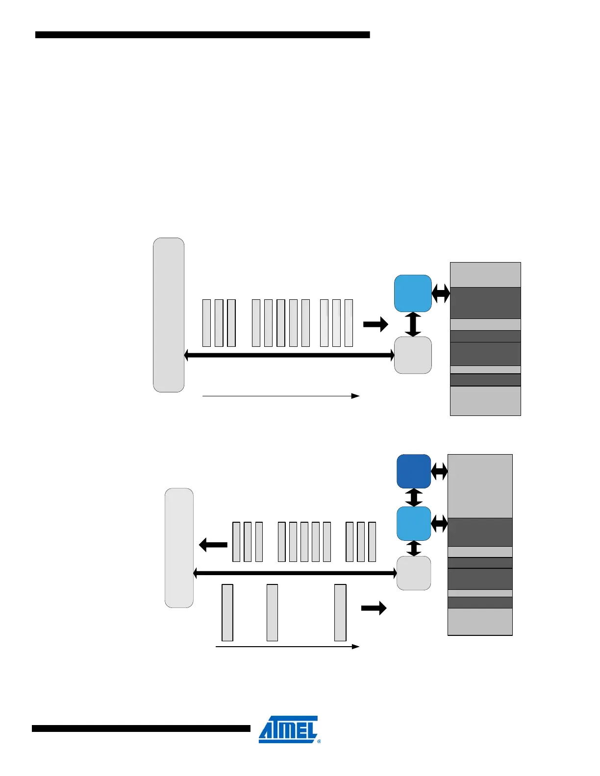
Figure 20-1. USB OUT transfer: data packet from host to USB device.
Figure 20-2. USB IN transfer: data packet from USB device to host after request from host.
Internal SRAM
USB
USB Endpoints
Configuration Table
USBEPPTR
USB
Buffers
ENDPOINT 1 DATA
ENDPOINT 2 DATA
ENDPOINT 3 DATA
D
A
T
A
0
D
A
T
A
0
D
A
T
A
0
D
A
T
A
1
D
A
T
A
0
D
A
T
A
1
D
A
T
A
0
D
A
T
A
1
D
A
T
A
0
D
A
T
A
1
D
A
T
A
0
BULK OUT
EPT 2
BULK OUT
EPT 3
BULK OUT
EPT 1
DP
DM
HOST
time
D
A
T
A
0
D
A
T
A
0
D
A
T
A
0
D
A
T
A
1
D
A
T
A
0
D
A
T
A
1
D
A
T
A
0
D
A
T
A
1
D
A
T
A
0
D
A
T
A
1
D
A
T
A
0
EPT 2EPT 3EPT 1
DP
DM
HOST
I
N
T
O
K
E
N
I
N
T
O
K
E
N
I
N
T
O
K
E
N
EPT 2 EPT 3 EPT 1
time
Internal SRAM
USB
USB Endpoints
Configuration Table
USBEPPTR
USB
Buffers
ENDPOINT 1 DATA
ENDPOINT 2 DATA
ENDPOINT 3 DATA
CPU

 Loading...


