275
8331B–AVR–03/12
Atmel AVR XMEGA AU
21.9 Register Description – TWI Master
21.9.1 CTRLA – Control register A
• Bit 7:6
– INTLVL[1:0]: Interrupt Level
These bits select the interrupt level for the TWI master interrupt, as described in ”Interrupts and
Programmable Multilevel Interrupt Controller” on page 134.
•Bit 5
– RIEN: Read Interrupt Enable
Setting the read interrupt enable (RIEN) bit enables the read interrupt when the read interrupt
flag (RIF) in the STATUS register is set. In addition the INTLVL bits must be nonzero for TWI
master interrupts to be generated.
•Bit 4
– WIEN: Write Interrupt Enable
Setting the write interrupt enable (WIEN) bit enables the write interrupt when the write interrupt
flag (WIF) in the STATUS register is set. In addition the INTLVL bits must be nonzero for TWI
master interrupts to be generated.
•Bit 3
– ENABLE: Enable TWI Master
Setting the enable TWI master (ENABLE) bit enables the TWI master.
• Bit 2:0
– Reserved
These bits are unused and reserved for future use. For compatibility with future devices, always
write these bits to zero when this register is written.
21.9.2 CTRLB
– Control register B
• Bit 7:4
– Reserved
These bits are unused and reserved for future use. For compatibility with future devices, always
write these bits to zero when this register is written.
• Bit 3:2
– TIMEOUT[1:0]: Inactive Bus Timeout
Setting the inactive bus timeout (TIMEOUT) bits to a nonzero value will enable the inactive bus
timeout supervisor. If the bus is inactive for longer than the TIMEOUT setting, the bus state logic
will enter the idle state.
Table 21-3 on page 276 lists the timeout settings.
Bit 76543210
+0x00 INTLVL[1:0] RIEN WIEN ENABLE – – –CTRLA
Read/Write R/W R/W R/W R/W R/W R R R
Initial Value00000000
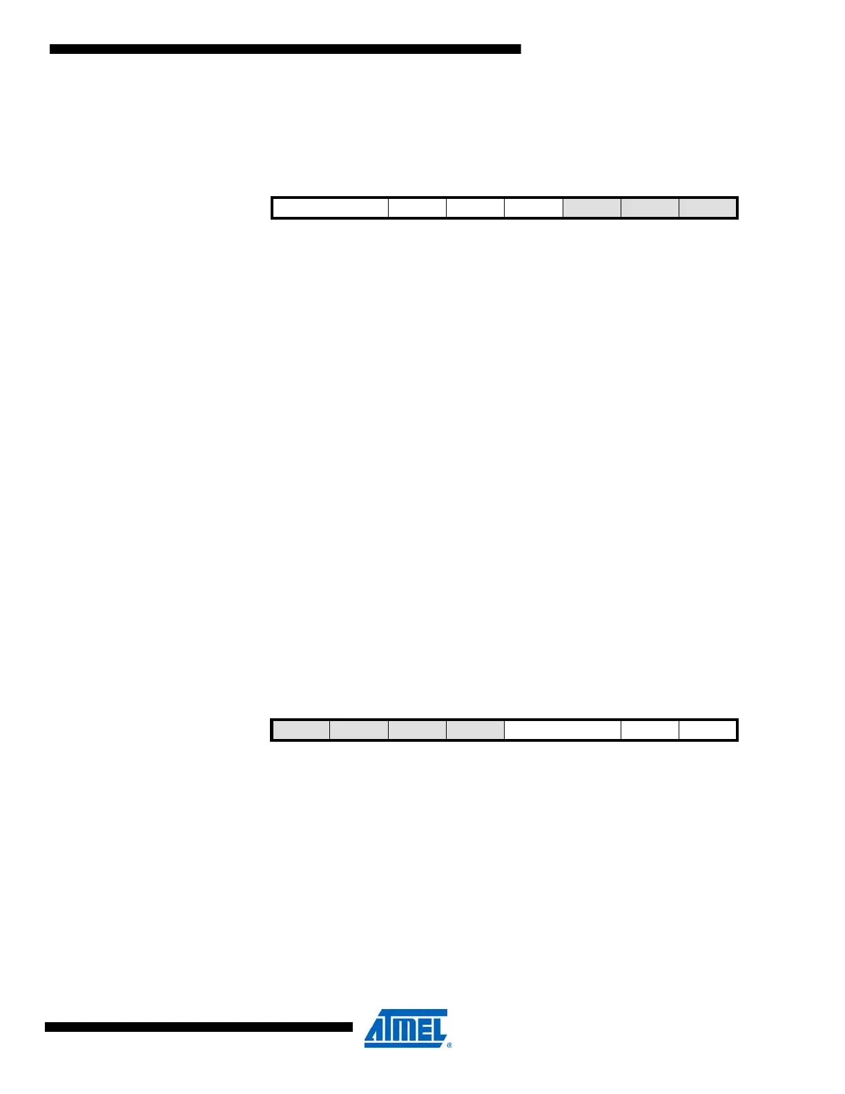
Bit 76543210
+0x01 – – – – TIMEOUT[1:0] QCEN SMEN CTRLB
Read/Write R R R R R/W R/W R/W R/W
Initial Value00000000

 Loading...


