361
8331B–AVR–03/12
Atmel AVR XMEGA AU
28.5 Voltage Reference Selection
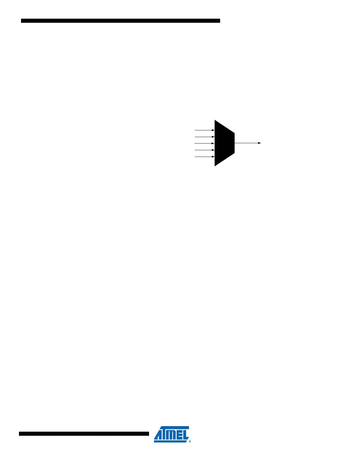
The following voltages can be used as the reference voltage (VREF) for the ADC:
• Accurate internal 1.00V voltage generated from the bandgap
• Internal V
CC
/1.6V voltage
• Internal V
CC
/2V voltage
• External voltage applied to AREF pin on PORTA
• External voltage applied to AREF pin on PORTB
Figure 28-8. ADC voltage reference selection
28.6 Conversion Result
The result of the analog-to-digital conversion is written to the corresponding channel result regis-
ters. The ADC is either in signed or unsigned mode. This setting is global for the ADC and all
ADC channels.
In signed mode, negative and positive results are generated. Signed mode must be used when
any of the ADC channels are set up for differential measurements. In unsigned mode, only sin-
gle-ended or internal signals can be measured. With 12-bit resolution, the TOP value of a signed
result is 2047, and the results will be in the range -2048 to +2047 (0xF800 - 0x07FF).
The ADC transfer function can be written as:
VINP and VINN are the positive and negative inputs to the ADC.
For differential measurements, GAIN is 1/2 to 64. For single-ended and internal measurements,
GAIN is always 1 and VINP is the internal ground.
In unsigned mode, only positive results are generated. The TOP value of an unsigned result is
4095, and the results will be in the range 0 to +4095 (0x0 - 0x0FFF).
The ADC transfer functions can be written as:
VINP is the single-ended or internal input.
The ADC can be configured to generate either an 8-bit or a 12-bit result. A result with lower res-
olution will be available faster. See the ”ADC Clock and Conversion Timing” on page 363 for a
description on the propagation delay.
The result registers are 16 bits wide, and data are stored as right adjusted 16-bit values. Right
adjusted means that the eight least-significant bits (lsb) are found in the low byte. A 12-bit result
Internal 1.00V
AREFB
AREFA
Internal VCC/1.6V
VREF
Internal VCC/2.0V
RES
VINP - VINN
VREF
---------------------------------
GAIN TOP +1()⋅⋅=
RES
VINP - (-ΔV)
VREF
--------------------------------- -
TOP +1()⋅=

 Loading...


