130
8331B–AVR–03/12
Atmel AVR XMEGA AU
11.6 Configuration Protection and Lock
The WDT is designed with two security mechanisms to avoid unintentional changes to the WDT
settings.
The first mechanism is the configuration change protection mechanism, employing a timed write
procedure for changing the WDT control registers. In addition, for the new configuration to be
written to the control registers, the register’s change enable bit must be written at the same time.
The second mechanism locks the configuration by setting the WDT lock fuse. When this fuse is
set, the watchdog time control register cannot be changed; hence, the WDT cannot be disabled
from software. After system reset, the WDT will resume at the configured operation. When the
WDT lock fuse is programmed, the window mode timeout period cannot be changed, but the
window mode itself can still be enabled or disabled.
11.7 Registers Description
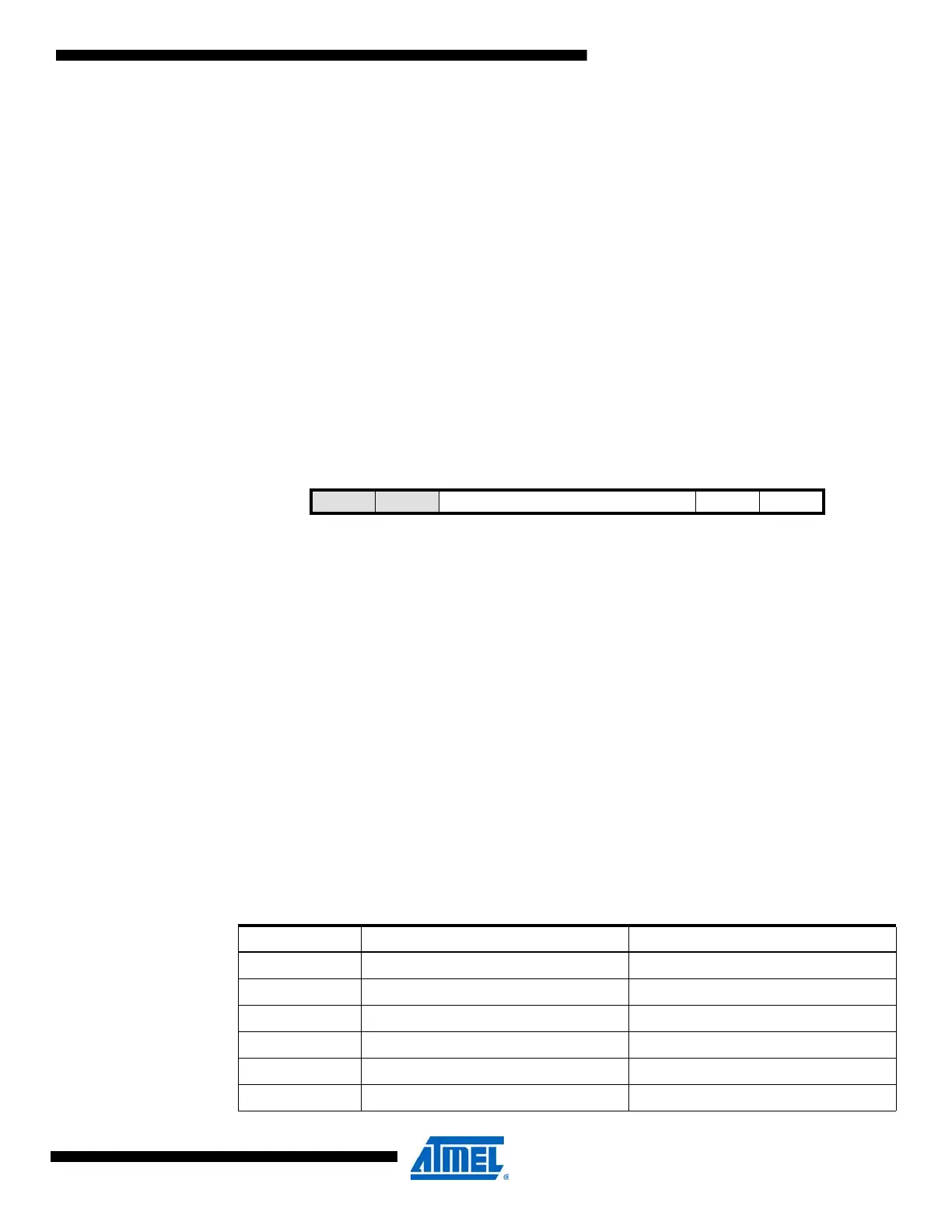
11.7.1 CTRL – Control register
• Bits 7:6 – Reserved
These bits are unused and reserved for future use. For compatibility with future devices, always
write these bits to zero when this register is written.
• Bits 5:2 – PER[3:0]: Timeout Period
These bits determine the watchdog timeout period as a number of 1kHz ULP oscillator cycles. In
window mode operation, these bits define the open window period. The different typical timeout
periods are found in Table 11-1. The initial values of these bits are set by the watchdog timeout
period (WDP) fuses, which are loaded at power-on.
In order to change these bits, the CEN bit must be written to 1 at the same time. These bits are
protected by the configuration change protection mechanism. For a detailed description, refer to
”Configuration Change Protection” on page 13.
Bit 76543210
+0x00 – – PER[3:0] ENABLE CEN CTRL
Read/Write
(unlocked)
R R R/W R/W R/W R/W R/W R/W
Read/Write
(locked)
RRRRRRRR
Initial Value
(x = fuse)
00XXXXX0
Table 11-1. Watchdog timeout periods .
PER[3:0] Group Configuration Typical Timeout Periods
0000 8CLK 8ms
0001 16CLK 16ms
0010 32CLK 32ms
0011 64CLK 64ms
0100 128CLK 0.128s
0101 256CLK 0.256s

 Loading...


