140
8331B–AVR–03/12
Atmel AVR XMEGA AU
12.7 Interrupt vector locations
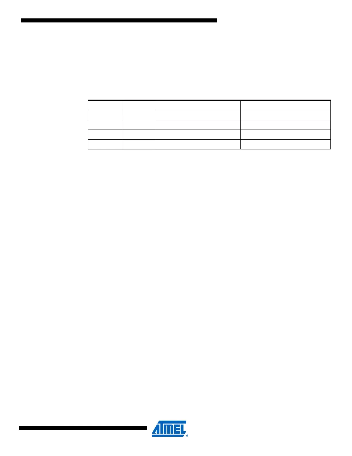
Table 12-2 on page 140 shows reset and Interrupt vectors placement for the various combina-
tions of BOOTRST and IVSEL settings. If the program never enables an interrupt source, the
Interrupt Vectors are not used, and regular program code can be placed at these locations. This
is also the case if the Reset Vector is in the Application section while the Interrupt Vectors are in
the Boot section or vice versa.
Table 12-2. Reset and Interrupt vectors placement
BOOTRST IVSEL Reset Address Interrupt Vectors Start Address
1 0 0x0000 0x0002
1 1 0x0000 Boot Reset Address + 0x0002
0 0 Boot Reset Address 0x0002
0 1 Boot Reset Address Boot Reset Address + 0x0002

 Loading...


