245
8331B–AVR–03/12
Atmel AVR XMEGA AU
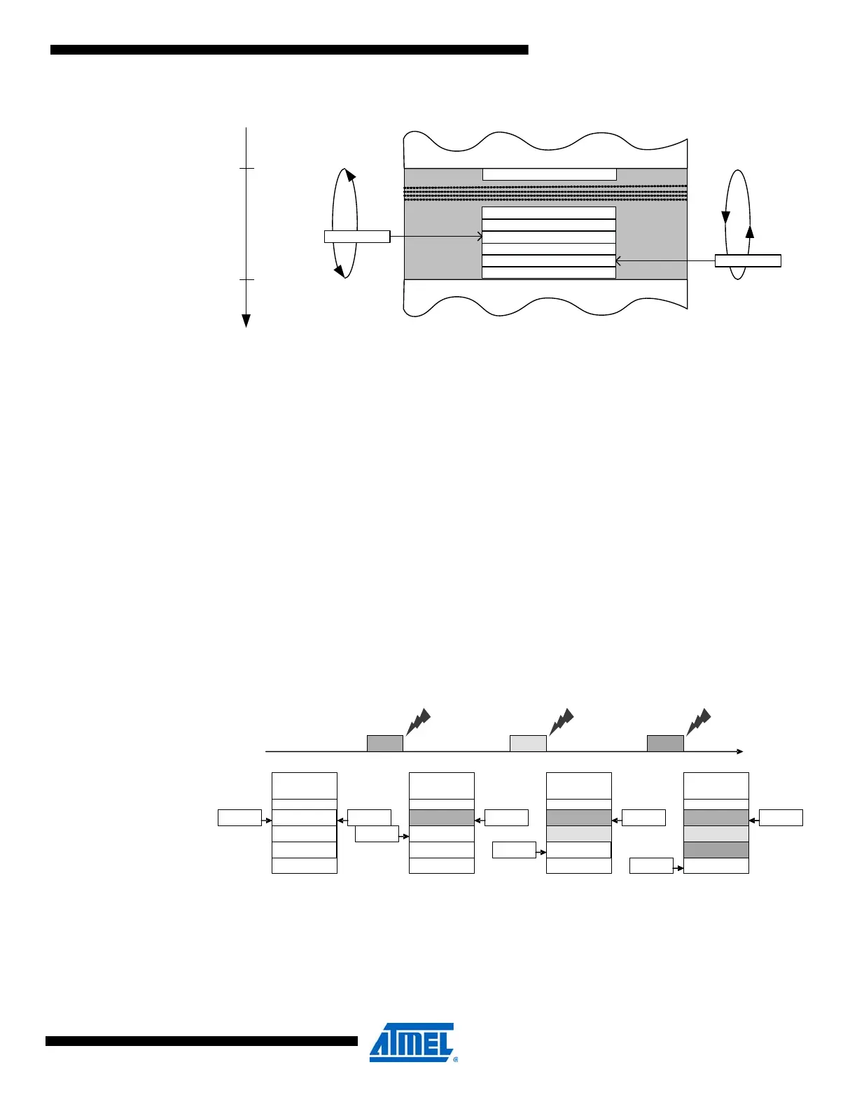
Figure 20-10. Transfer complete FIFO.
To manage the FIFO, a five-bit write pointer (FIFOWP) and five-bit read pointer (FIFORP) are
used by the USB module and application software, respectively. FIFORP and FIFOWP are one's
complemented, and thus hold negative values. The SRAM location of the data is the sum of
EPPTR and the read or write pointer. The number of items in the FIFO is the difference between
FIFOWP and FIFORP. For the programmer, the FIFORP and FIFOWP values have to be cast to
a signed 8-bit integer, and then the offset into the FIFO from this signed integer must be
deducted.
The transaction complete interrupt flag (TRNIF) in the INFLAGSB[CLR,SET] register is set to
indicate a non-empty FIFO when FIFORP != FIFOWP, cleared when they are equal, and also
set when the FIFO is full.
Each time an endpoint IN or OUT transaction completes successfully, its endpoint configuration
table address is stored in the FIFO at the current write pointer position (i.e., EPPTR + 2 ×
FIFOWP) and FIFOWP is decremented. When the pointer reaches the FIFO size, it wraps to
zero. When application software reads FIFORP, this is decremented in the same way. Reading
the write pointer has no effect. The endpoint configuration table address can then be read
directly from (EPPTR + 2 × FIFORP).
Figure 20-11. USB transaction complete FIFO example.
20.10 Interrupts and Events
The USB module can generate interrupts and events. The module has 10 interrupt sources.
These are split between two interrupt vectors, the transaction complete (TRNCOMPL) interrupt
and the bus event (BUSEVENT) interrupt. An interrupt group is enabled by setting its interrupt
level (INTLVL), while different interrupt sources are enabled individually or in groups.
USB_TC_ FIFO
TC
_
EP
_
ADDRH
_
0
TC_EP_ ADDRL_0
TC_ EP_ ADDRH_MAX
ENDPOINT DESCRIPTOR TABLE
TC_EP_ ADDRH_1
TC_EP_ ADDRL_1
INTERNAL SRAM
TC_EP_ ADDRH_2
TC_ EP_ ADDRH_2
FIFOWP
FIFORP
EPPTR
SRAM
ADDRESS
EPPTR
–
4x( MAXEP+1)
Ep X
t
EpY
Ep Z
FIFO
X
Y
Z
FIFOWP
FIFORP
X
Y
Z
FIFOWP
FIFORP
FIFO
X
Y
FIFOWP
FIFORP
FIFO
X
FIFOWP
FIFORP
FIFO
FIFOWP FIFORP

 Loading...


