170
8331B–AVR–03/12
Atmel AVR XMEGA AU
“compare channels.” When used for capture operations, the CC channels are referred to as
“capture channels.”
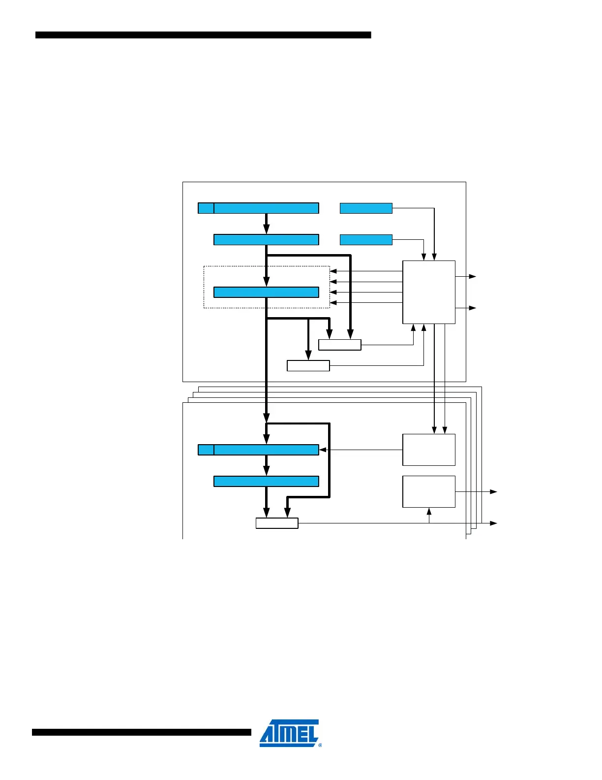
14.3 Block Diagram
Figure 14-2 on page 170 shows a detailed block diagram of the timer/counter without the
extensions.
Figure 14-2. Timer/counter block diagram.
The counter register (CNT), period registers with buffer (PER and PERBUF), and compare and
capture registers with buffers (CCx and CCxBUF) are 16-bit registers. All buffer register have a
buffer valid (BV) flag that indicates when the buffer contains a new value.
During normal operation, the counter value is continuously compared to zero and the period
(PER) value to determine whether the counter has reached TOP or BOTTOM.
The counter value is also compared to the CCx registers. These comparisons can be used to
generate interrupt requests, request DMA transactions or generate events for the event system.
The waveform generator modes use these comparisons to set the waveform period or pulse
width.
Base Counter
Compare/Capture
(Unit x = {A,B,C,D})
Counter
=
CCx
CCBUFx
Waveform
Generation
BV
=
PERBUF
PER
CNT
BV
= 0
"count"
"clear"
"direction"
"load"
Control Logic
CTRLD
CTRLA
OVF/UNF
(INT/DMA Req.)
ERRIF
(INT Req.)
TOP
"match"
CCxIF
(INT/DMA
Req.)
Control Logic
Clock Select
"ev"
UPDATE
BOTTOM
OCx Out
Event
Select

 Loading...


