401
8331B–AVR–03/12
Atmel AVR XMEGA AU
30.9 Register Description
30.9.1 ACnCTRL – Analog Comparator n Control register
• Bit 7:6 – INTMODE[1:0]: Interrupt Modes
These bits configure the interrupt mode for analog comparator n according to Table 30-1.
• Bit 5:4 – INTLVL[1:0]: Interrupt Level
These bits enable the analog comparator n interrupt and select the interrupt level, as described
in ”Interrupts and Programmable Multilevel Interrupt Controller” on page 134. The enabled inter-
rupt will trigger according to the INTMODE setting.
• Bit 3 – HSMODE: High-Speed Mode Select
By default, the analog comparator is in low-power mode, and this bit is zero. Setting this bit
selects high-speed mode for a shorter propagation delay. For details on actual performance,
refer to device datasheet.
• Bit 2:1 – HYSMODE[1:0]: Hysteresis Mode Select
These bits select the hysteresis mode according to Table 30-2. For details on actual hysteresis
levels, refer to the device datasheet.
• Bit 0 – ENABLE: Enable
Setting this bit enables analog comparator n.
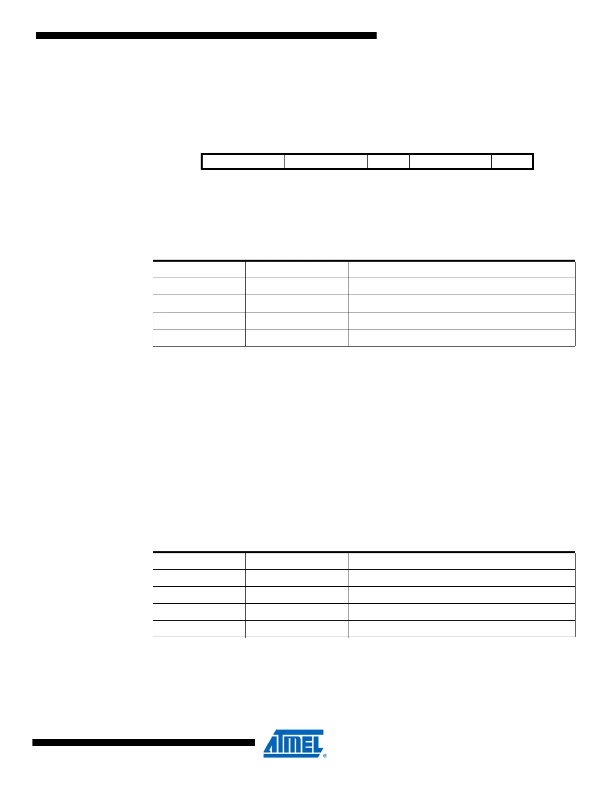
Bit 76543210
+0x00 / +0x01 INTMODE[1:0] INTLVL[1:0] HSMODE HYSMODE[2:0] ENABLE ACnCTRL
Read/Write R/W R/W R/W R/W R/W R/W R/W R/W
Initial Value 0 0 0 0 0 0 0 0
Table 30-1. Interrupt settings.
INTMODE[1:0] Group Configuration Description
00 BOTHEDGES Comparator interrupt or event on output toggle
01
–
Reserved
10 FALLING Comparator interrupt or event on falling output edge
11 RISING Comparator interrupt or event on rising output edge
Table 30-2. Hysteresis settings.
HYSMODE[1:0] Group Configuration Description
00 NO No hysteresis
01 SMALL Small hysteresis
10 LARGE Large hysteresis
11 – Reserved

 Loading...


