402
8331B–AVR–03/12
Atmel AVR XMEGA AU
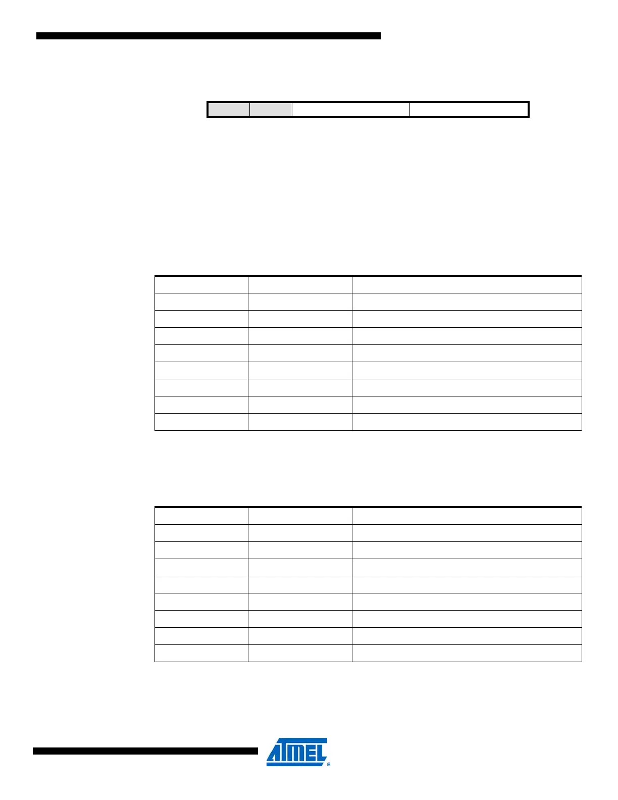
30.9.2 ACnMUXCTRL – Analog Comparator n Mux Control register
• Bit 7:6 – Reserved
These bits are unused and reserved for future use. For compatibility with future devices, always
write these bits to zero when this register is written.
• Bit 5:3 – MUXPOS[2:0]: Positive Input MUX Selection
These bits select which input will be connected to the positive input of analog comparator n
according to Table 30-3.
• Bit 2:0 – MUXNEG[2:0]: Negative Input MUX Selection
These bits select which input will be connected to the negative input of analog comparator n
according to Table 30-4 on page 402.
Bit 7 6 543210
+0x02 / +0x03
–
– MUXPOS[2:0] MUXNEG[2:0] ACnMUXCTRL
Read/Write R R R/W R/W R/W R/W R/W R/W
Initial Value 0 0 0 0 0 0 0 0
Table 30-3. Positive input MUX selection.
MUXPOS[2:0] Group Configuration Description
000 PIN0 Pin 0
001 PIN1 Pin 1
010 PIN2 Pin 2
011 PIN3 Pin 3
100 PIN4 Pin 4
101 PIN5 Pin 5
110 PIN6 Pin 6
111 DAC DAC output
Table 30-4. Negative input MUX selection.
MUXNEG[2:0] Group Configuration Negative Input MUX Selection
000 PIN0 Pin 0
001 PIN1 Pin 1
010 PIN3 Pin 3
011 PIN5 Pin 5
100 PIN7 Pin 7
101 DAC DAC output
110 BANDGAP Internal bandgap voltage
111 SCALER V
CC
voltage scaler

 Loading...


