346
8331B–AVR–03/12
Atmel AVR XMEGA AU
27.10 Register Description – EBI
27.10.1 CTRL – Control register
• Bit 7:6 – SDDATAW[1:0]: SDRAM Data Width Setting
These bits select the EBI SDRAM data width configuration, according to Table 27-8 on page
346.
Note: 1. Eight-bit data bus only available for four-port EBI interface
• Bit 5:4 – LPCMODE[1:0]: SRAM Low Pin Count Mode
These bits select the EBI SRAM LPC configuration according to Table 27-9 on page 346
• Bit 3:2 – SRMODE[1:0]: SRAM Mode
These bits selects the EBI SRAM configuration according to Table 27-10 on page 346.
Note: 1. ALE2 and NOALE only available with 4-port EBI interface
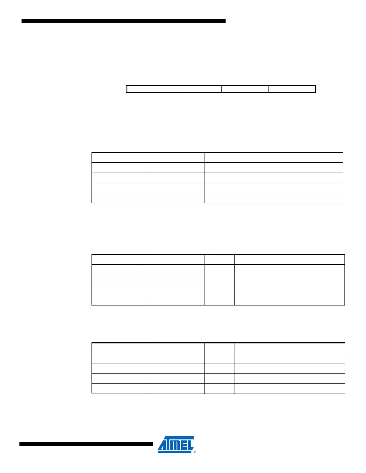
Bit 76543210
+0x00 SDDATAW[1:0] LPCMODE[1:0] SRMODE[1:0] IFMODE[1:0] CTRL
Read/Write R/W R/W R/W R/W R/W R/W R/W R/W
Initial Value 0 0 0 0 0 0 0 0
Table 27-8. SDRAM Mode.
SDDATAW[1:0] Group Configuration Description
00 4BIT Four-bit data bus
01 8BIT
(1)
Eight-bit data bus
10 – Reserved
11 – Reserved
Table 27-9. SRAM LPC Mode.
LPCMODE[1:0] Group Configuration ALE Description
00 ALE1 ALE1 Data multiplexed with Address byte 0
01 – – Reserved
10 ALE1 & 2 Data multiplexed with Address byte 0 and 1ALE12
11 – – Reserved
Table 27-10. SRAM Mode.
SRMODE[1:0] Group Configuration ALE Description
00 ALE1 ALE1 Address byte 0 and 1 multiplexed
01 ALE2
(1)
ALE2 Address byte 0 and 2 multiplexed
10 ALE12
(1)
ALE1 & 2 Address byte 0, 1 and 2 multiplexed
11 NOALE No ALE No address multiplexing

 Loading...


