347
8331B–AVR–03/12
Atmel AVR XMEGA AU
• Bit 1:0 – IFMODE[1:0]: Interface Mode
These bits select EBI interface mode and the number of ports that should be enabled and over-
ridden for EBI, according to Table 27-11 on page 347.
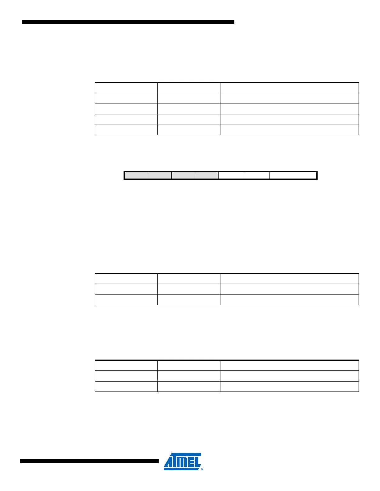
27.10.2 SDRAMCTRLA – SDRAM Control register A
• Bit 7:4 – Reserved
These bits are unused and reserved for future use.
• Bit 3 – SDCAS: SDRAM CAS Latency
This bit sets the CAS latency as a number of Clk
PER2
cycles. By default this bit is zero and the
CAS latency is two Clk
PER2
cycles. When this bit is set to one, the CAS latency is three Clk
PER2
cycles.
• Bit 2 – SDROW: SDRAM Row Bits
This bit sets the number of row bits used for the connected SDRAM. By default this bit is zero,
and the row bit setting is set to 11 row bits. When this bit is set to one, the row bit setting is set to
12 row bits.
• Bit 1:0 – SDCOL[1:0]: SDRAM Column Bits
These bits select the number of column bits that are used for the connected SDRAM according
to table.Table 27-14 on page 348.
Table 27-11. EBI Mode
IFMODE[1:0] Group Configuration Description
00 DISABLED EBI disabled
01 3PORT EBI enabled with three-port interface
10 4PORT EBI enabled with four-port interface
11 2PORT EBI enabled with two-port interface
Bit 7654 3 2 10
+0x01
– – – – SDCAS SDROW SDCOL[1:0] SDRAMCTRLA
Read/Write R R R R R/W R/W R/W R/W
Initial Value0000 0 0 00
Table 27-12. SDRAM CAS latency.
SDROW Group Configuration Description
0 2CLK 2 Clk
PER2
cycles delay
1 3CLK 3 Clk
PER2
cycles delay
Table 27-13. SDRAM row bits.
SDROW Group Configuration Description
0 11BIT 11 row bits
1 12BIT 12 row bits
 Loading...


