447
8331B–AVR–03/12
Atmel AVR XMEGA AU
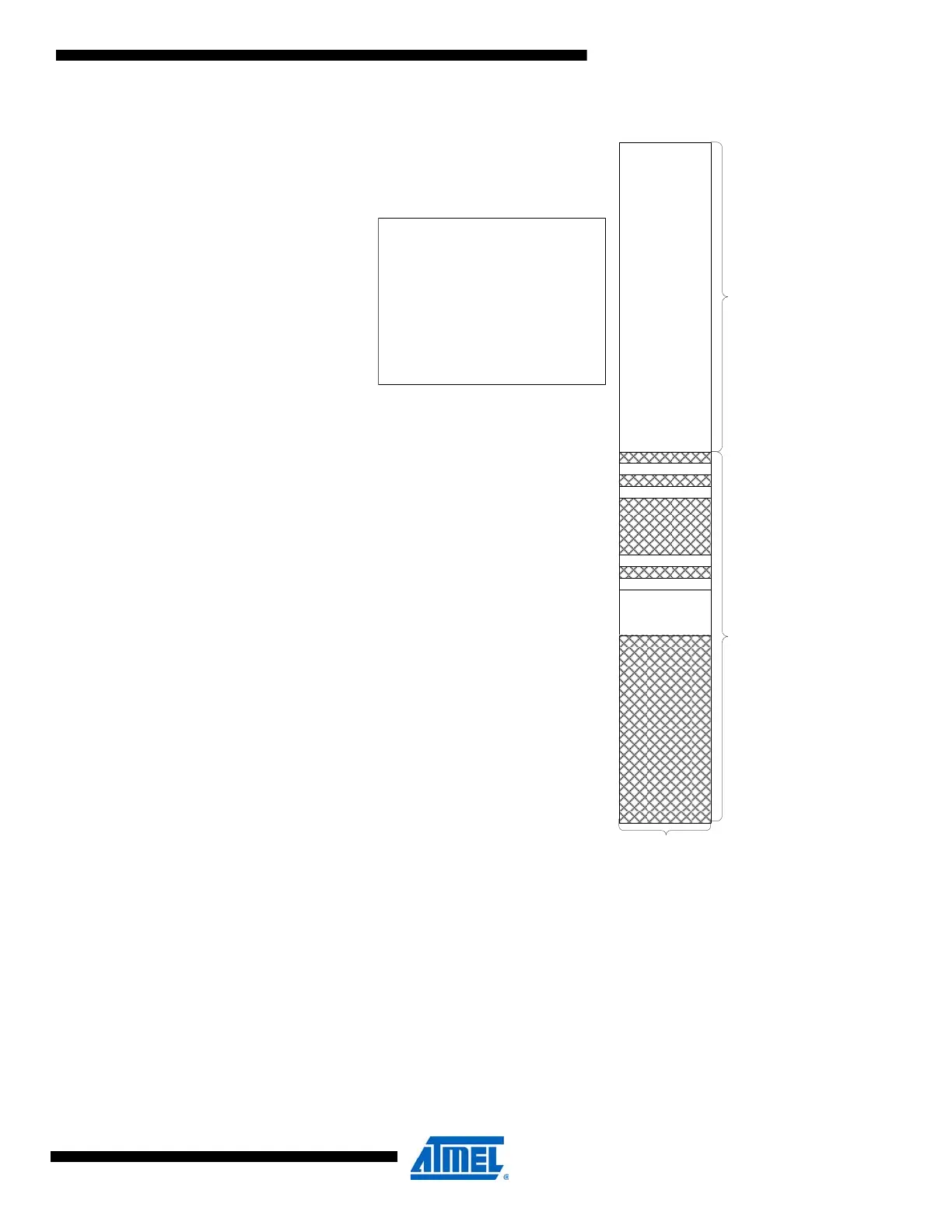
Figure 33-3. Memory map for PDI accessing the data and program memories.
33.12.1 Enabling External Programming Interface
NVM programming from the PDI requires enabling using the following steps:
1. Load the RESET register in the PDI with 0x59.
2. Load the NVM key in the PDI.
3. Poll NVMEN in the PDI status register (PDI STATUS) until NVMEN is set.
When the NVMEN bit in the PDI STATUS register is set, the NVM interface is enabled and
active from the PDI.
33.12.2 NVM Programming
When the PDI NVM interface is enabled, all memories in the device are memory mapped in the
PDI address space. The PDI controller does not need to access the NVM controller's address or
FLASH_BASE = 0x0800000
EPPROM_BASE = 0x08C0000
FUSE_BASE = 0x08F0020
DATAMEM_BASE = 0x1000000
APP_BASE = FLASH_BASE
BOOT_BASE = FLASH_BASE + SIZE_APPL
PROD_SIGNATURE_BASE = 0x008E0200
USER_SIGNATURE_BASE = 0x008E0400
0x0000000
FUSES
APPLICATION
SECTION
16 MB
BOOT SECTION
0x0800000
0x08F0020
TOP=0x1FFFFFF
EEPROM
0x08E0200
SIGNATURE ROW
0x08C0000
0x08C1000
DATAMEM
(mapped IO/SRAM)
16 MB
0x1000000
1 BYTE

 Loading...


