73
8331B–AVR–03/12
Atmel AVR XMEGA AU
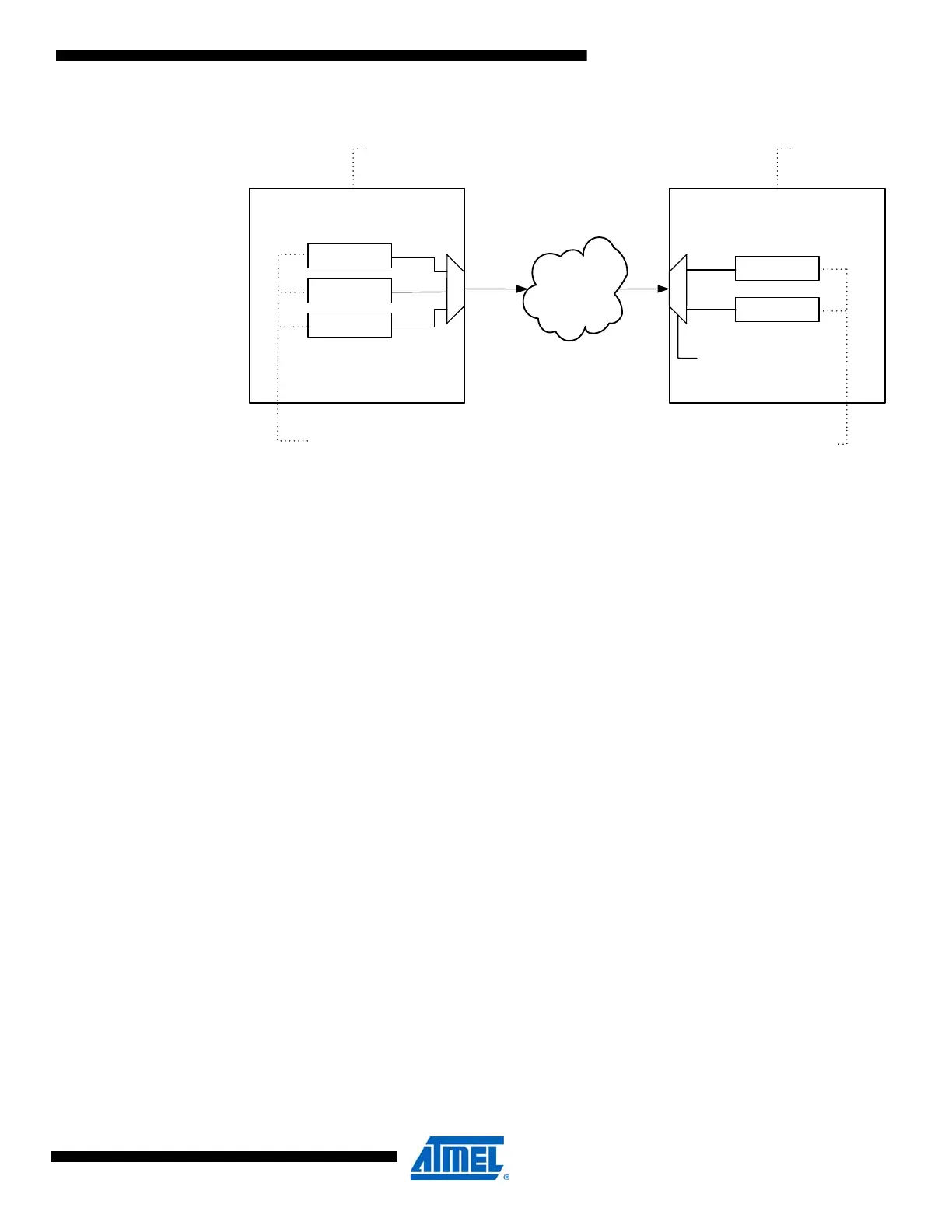
Figure 6-2. Example of event source, generator, user, and action.
Events can also be generated manually in software.
6.3.1 Signaling Events
Signaling events are the most basic type of event. A signaling event does not contain any infor-
mation apart from the indication of a change in a peripheral. Most peripherals can only generate
and use signaling events. Unless otherwise stated, all occurrences of the word ”event” are to be
understood as meaning signaling events.
6.3.2 Data Events
Data events differ from signaling events in that they contain information that event users can
decode to decide event actions based on the receiver information.
Although the event routing network can route all events to all event users, those that are only
meant to use signaling events do not have decoding capabilities needed to utilize data events.
How event users decode data events is shown in Table 6-1 on page 74.
Event users that can utilize data events can also use signaling events. This is configurable, and
is described in the datasheet module for each peripheral.
6.3.3 Peripheral Clock Events
Each event channel includes a peripheral clock prescaler with a range from 1 (no prescaling) to
32768. This enables configurable periodic event generation based on the peripheral clock. It is
possible to periodically trigger events in a peripheral or to periodically trigger synchronized
events in several peripherals. Since each event channel include a prescaler, different peripher-
als can receive triggers with different intervals.
6.3.4 Software Events
Events can be generated from software by writing the DATA and STROBE registers. The DATA
register must be written first, since writing the STROBE register triggers the operation. The
DATA and STROBE registers contain one bit for each event channel. Bit n corresponds to event
channel n. It is possible to generate events on several channels at the same time by writing to
several bit locations at once.
Event
Routing
Network
|
Compare Match
Over-/Underflow
Error
Timer/Counter
Channel Sweep
Single
Conversion
ADC
Event Generator
Event Source
Event User
Event Action
Event Action Selection

 Loading...


