Chapter 4: AC Drive Parameters
Page 4–45
DURApulse GS4 AC Drive User Manual – 1st Ed, Rev A - 10/20/2017
Type Hex Addr Dec Addr
P1.19 Skip Frequency 1 Upper Limit
R/W 0113 40276
Range/Units (Format: 16-bit unsigned) Default
0�00~600�00 Hz
0
Type Hex Addr Dec Addr
P1.20 Skip Frequency 1 Lower Limit
R/W 0114 40277
Range/Units (Format: 16-bit unsigned) Default
0�00~600�00 Hz
0
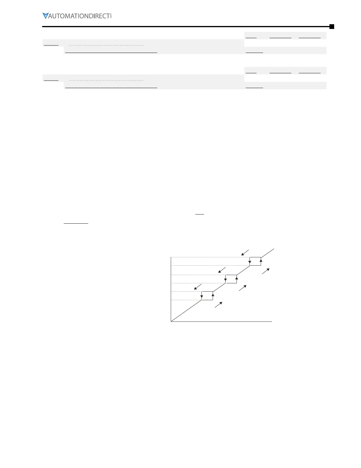
These parameters (P1.19~P1.24) are used to set skip frequency zones for the GS4 drive, but the
frequency output is continuous. These skip frequencies are useful when a motor has vibration at
specific frequency bandwidths. The vibration can be avoided by skipping these frequencies, and
the GS4 offers three Skip Frequency zones for this purpose.
•
The limits (other than 0.0) of these three zones are parameters P1.19 ≥ P1.20 ≥ P1.21 ≥ P1.22 ≥
P1.23 ≥ P1.24.
•
Do not overlap Skip Frequencies�
•
An individual skip frequency will be ignored when both Upper and Lower Limit are set to 0�0 (i�e�,
Skip Frequencies 1 and 3 can be active, even if Skip Frequency 2 limits are set to 0�0)�
•
The commanded frequency for the drive can be set within the range of these Skip Frequency
Upper and Lower Limits� At this moment, the actual output frequency of the drive will be limited
by the Skip Frequency Limit settings�
•
When accelerating/decelerating, the output frequency will still pass through the range of skip
frequencies according to Accel and Decel Times�
•
These values can only be set when the drive is not in RUN�
Example: Set P1.19 = 10Hz. Set P1.20 = 5Hz. When following an analog input command, the
drive’s output frequency will not follow the input command between 5Hz and 10Hz. When
accelerating, the drive output will remain at 5Hz until the command increases above 10Hz. When
decelerating, the drive output will remain at 10Hz until the command signal falls below 5Hz.
0
P1.19
P1.20
P1.21
P1.22
P1.23
P1.24
Internal
frequency
command
Frequency setting command
rising frequency
falling freq uency

 Loading...
