Page 4–112
DURApulse GS4 AC Drive User Manual – 1st Ed, Rev A - 10/20/2017
Chapter 4: AC Drive Parameters
analog inPut ParaMeter exaMPles
Refer to the following equations and examples for changing the ratio of the analog input signal
relative to the output frequency of the drive.
Use the equations below when calculating the values for the Drive Maximum Output Frequency,
Analog Input Offset, Analog Input Gain, and the Mid-point Frequency.
A) Drive Maximum Output Frequency = P0.04 = ((Desired Max RPM)/(Base RPM)) x Base Freq
B) Analog Offset % = AIx Input Bias
(Input bias determines the offset)
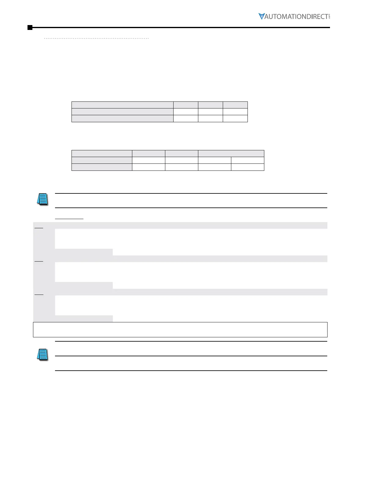
Analog Input (AIx) AI1 AI2 AI3
AIx Bias (Offset) Parameter
P4�10 P4�15 P4�19
AIx Bias (Offset) Polarity Parameter
P4�11 P4�16 P4�20
Determine your required settings for these parameters as follows:
Ana log Offset (Bias) = ( DesiredOffsetFreq / MaxFreqOut ) x 100
C) Analog Gain % = AIx Input Gain
Analog Input AI1 AI2 AI3
Polarity
Positive (+) Positive (+) Positive (+) Negative (-)
AIx Gain Parameter
P4�12 P4�17 P4�21 P4�22
[(Max Freq Reference - Min Freq Reference) / P0.04] x 100
D) Mid-point Frequency = [(Max Freq Reference - Min Freq Reference) / 2] + Min Freq Reference
The Mid-point Frequency calculation shows the frequency reference of the drive when the
potentiometer or other analog input device is at its mid-point.
Equations
AI1
P4.10
thru
P4.12
Offset Polarity Analog Command Calculation
Positive P4�11=1 Fr equency Output (Hz) = [ (Analog_In%*) x (Gain%) + (Bias%) ] x Max_Out (Hz)
Negative P4�11=2 Fr equency Output (Hz) = [ (Analog_In%*) x (Gain%) - (Bias%) ] x Max_Out (Hz)
Calculation by Parameter #s
Fr equency Output (Hz) = [ (AI
(volts)
/ 10) x (P4�12) ± (P4�10) ] x (P0�04)
AI2
P4.15
thru
P4.17
Offset Polarity Analog Command Calculation
Positive P4�16=1 Fr equency Output (Hz) = [ (Analog_In%*) x (Gain%) + (Bias%) ] x Max_Out (Hz)
Negative P4�16=2 Fr equency Output (Hz) = [ (Analog_In%*) x (Gain%) - (Bias%) ] x Max_Out (Hz)
Calculation by Parameter #s
Fr equency Output (Hz) = [ (AI
(volts)
/ 10) x (P4�17) ± (P4�15) ] x (P0�04)
AI3
P4.19
thru
P4.22
Offset Polarity Analog Command Calculation
Positive P4�20=1 Fr equency Output (Hz) = [ (Analog_In%*) x (Gain%) + (Bias%) ] x Max_Out (Hz)
Negative P4�20=2 Fr equency Output (Hz) = [ (Analog_In%*) x (Gain%) - (Bias%) ] x Max_Out (Hz)
Calculation by Parameter #s
Fr equency Output (Hz) = [ (AI
(volts)
/ 10) x (P4�21 or P4�22) ± (P4�19) ] x (P0�04)
* Analog_In% = Analog_Signal
(volts)
/ 10 → for 0~10V inputs
Analog_Signal
(mA)
/ 20 → for 0~20mA or 4~20mA inputs
For AI1, AI2, and AI3: P4.24 (AI V/Hz Calculated Selection) MUST BE SET TO ZERO (All Inputs
Use Bias and Gain) TO ENABLE BIAS AND GAIN CALCULATIONS.
For AI3: Gain% is dependent on P4.20 setting. If P4.20=1 use P4.21 for Gain% calculation. If
P4.20=2, use P4.22 for Gain% calculation.

 Loading...
