Chapter 4: AC Drive Parameters
Page 4–113
DURApulse GS4 AC Drive User Manual – 1st Ed, Rev A - 10/20/2017
analog inPut ParaMeter exaMPle 1: standard oPeration
This example illustrates the default operation of the drive. The example is given to further
illustrate the use of the analog calculations. The full range of the analog input signal corresponds
to the full forward frequency range of the AC drive.
•
Minimum Frequency Reference = 0Hz
•
Maximum Frequency Reference = 60 Hz
For AI1, AI2, and AI3: P4.24 (AI V/Hz Calculated Selection) MUST BE SET TO ZERO (All Inputs
Use Bias and Gain) TO ENABLE BIAS AND GAIN CALCULATIONS.
Calculations (see page 4–112 for formulas)
A) Drive Maximum Output Frequency = P0.04 = (1750 rpm / 1750 rpm) x 60Hz = 60Hz
B) Analog Offset % = ( 0Hz / 60Hz ) x 100 = 0%
Analog Input (AIx) AI1 AI2 AI3
AIx Bias Parameter
P4�10 P4�15 P4�19
C) Analog Gain % = [(60Hz - 0Hz) / 60Hz] x 100 = 100% = AIx Input Gain
Analog Input AI1 AI2 AI3
Polarity
Positive (+) Positive (+) Positive (+) Negative (-)
AIx Gain Parameter
P4�12 P4�17 P4�21 P4�22
D) Mid-point Frequency = [(60Hz - 0Hz) / 2] + 0Hz = 30Hz
Parameter Settings
Analog Input AI1 or AI2 or AI3
Parameter Settings
Polarity
Positive (+) Positive (+) Positive (+) Negative (-)
AIx Bias Parameter
P4�10 P4�15 P4�19 0�0%
AIx Polarity Parameter
P4�11 P4�16 P4�20 0: No Offset
AIx Gain Parameter
P4�12 P4�17 P4�21 P4�22 100�0%
Reverse Run Parameter
P4�09 0: Digital FWD/REV
Drive Max Output Freq
P0�04 60Hz
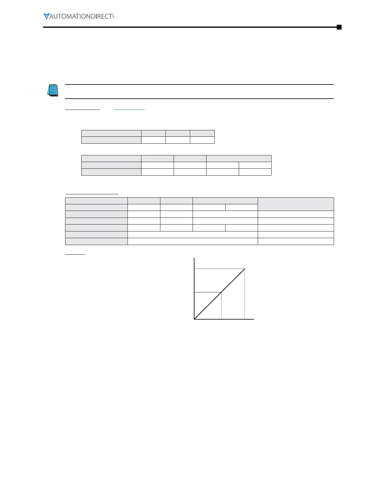
Results
Output
Frequency
0Hz
60Hz
30Hz
0V 5V 10V
-10V0V 10V
0mA10mA 20mA

 Loading...
